| CPC A01F 12/185 (2013.01) [A01F 7/06 (2013.01); A01F 12/181 (2013.01); A01F 12/20 (2013.01); A01F 12/22 (2013.01)] | 19 Claims |

|
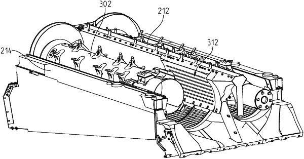
1. A harvesting machine, comprising:
a first rotor rotationally coupled to a chassis about a first axis;
a first cover element and a first concave positioned partially around the first rotor to partially define a first cavity for the first rotor;
a second rotor rotationally coupled to the chassis about a second axis;
a second cover element and a second concave positioned partially around the second rotor to partially define a second cavity for the second rotor; and
a spine separating the first rotor from the second rotor and having a first surface and a second surface, the first and second surface being solid, the spine providing structural support with the chassis;
wherein, the spine is coupled to the first cover element and the first concave to partially define the first cavity and the spine is coupled to the second cover element and the second concave to partially define the second cavity;
wherein the spine has threshing inserts coupled directly to the first surface and the second surface to facilitate threshing of crop processed by the first and second rotors;
wherein each of the threshing inserts extend parallel with the first and second axis along a threshing section of the spine.
|