| CPC H02K 7/14 (2013.01) [B25J 17/0208 (2013.01)] | 10 Claims |

|
1. A compensating element, comprising:
a first assembly;
a second assembly, the first and second assemblies at least partially arranged next to each other in a direction of a center axis of the compensating element; and
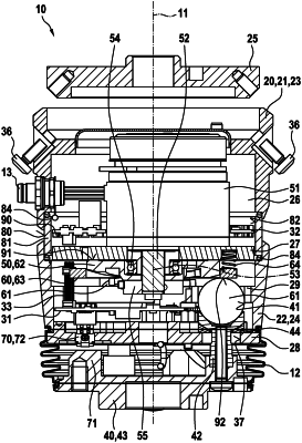
a locking mechanism configured to be switched between a first operating state, in which the first assembly is connected fixedly to the second assembly and the first operating state defines a zero position between the first and second assemblies, and a second operating state in which the first and second assemblies are connected to each other via a spring mechanism in such a manner that the first and second assemblies are movable relative to each other, the locking mechanism comprising:
an electric motor configured to switch the locking mechanism over between the first and the second operating states;
at least three balls arranged within the first assembly and distributed about the center axis;
a locking ring arranged concentrically with respect to the center axis and on a side of the at least three balls that faces away from the second assembly, the locking ring being selectively braced and not braced against the at least three balls depending on a rotational position of the locking ring with respect to the center axis; and
a torsion spring via which the locking ring is connected in terms of rotary drive to the electric motor, the torsion spring rotationally elastic about the center axis,
wherein:
the electric motor has a rotatable drive journal arranged concentrically with respect to the center axis,
the locking ring surrounds the drive journal, and
the torsion spring is arranged between the drive journal and the locking ring, as viewed radially with respect to the center axis.
|