| CPC H01F 38/30 (2013.01) [H01F 3/10 (2013.01); H01F 27/24 (2013.01); H01F 41/0246 (2013.01)] | 9 Claims |

|
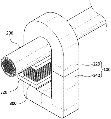
1. A core for a current transformer, comprising:
an upper core curved in a semi-circular shape to have a receiving groove formed therein, and having both ends extended downwards to be disposed to be spaced apart from each other;
a lower core disposed on a lower portion of the upper core, and having both ends extended upwards to be disposed to face the both ends of the upper core; and
a bobbin in which a coil is wound and mounted on the lower core,
wherein the receiving groove receives all the cross sections of a power line,
wherein the lower core comprises:
a lower base;
a first lower extension portion extended in the direction of the upper core from the lower base; and
a second lower extension portion spaced apart from the first lower extension portion, and extended in the direction of the upper core from the lower base, and
wherein the bobbin is mounted on one of the first lower extension portion and second lower extension portion, and
wherein the power line is received adjacent to an outer circumference of the receiving groove of the upper core.
|