| CPC G06T 7/0008 (2013.01) [B25J 15/0004 (2013.01); G01B 21/02 (2013.01); G06T 7/0004 (2013.01); G06T 7/0006 (2013.01); G06T 7/66 (2017.01); H04N 3/155 (2013.01); H04N 23/72 (2023.01); G05B 2219/39478 (2013.01); G06T 2207/30148 (2013.01); G06T 2207/30164 (2013.01)] | 14 Claims |

|
1. An inspection method for a pillar-shaped honeycomb structure, comprising:
a step of preparing a pillar-shaped honeycomb structure made of ceramic, which comprises a first end surface, a second end surface, and a side surface;
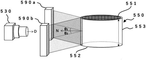
a step A of generating a plurality of strip-shaped images by repeatedly capturing the side surface part by part with an area camera for the side surface while relatively moving the area camera for the side surface with respect to the pillar-shaped honeycomb structure so that the area camera for the side surface orbits the side surface of the pillar-shaped honeycomb structure; and
a step B of determining presence or absence of defects on the side surface based on the strip-shaped images obtained in the step A;
wherein
a number of the strip-shaped images generated in the step A is sufficient to cover the entire side surface;
a shutter speed when the area camera for the side surface captures a part of the side surface for generating a single strip-shaped image is 10 to 1000 μsec; and
each of the strip-shaped images has a length covering the entire height of the pillar-shaped honeycomb structure in a longitudinal direction, and a length of 1 to 10 mm in a width direction; and
in the step A, when the area camera for the side surface orbits the side surface of the pillar-shaped honeycomb structure, an imaging distance, which is a distance in a capturing direction between the side surface and the area camera for the side surface, is monitored with a displacement meter, and the area camera for the side surface is relatively moved with respect to the side surface of the pillar-shaped honeycomb structure so that a change in the imaging distance is within ±2 mm.
|