| CPC G01N 29/07 (2013.01) [E21B 33/05 (2013.01); E21B 47/00 (2013.01); G01N 29/223 (2013.01); G01N 29/28 (2013.01); G01N 2291/0258 (2013.01); G01N 2291/02854 (2013.01)] | 17 Claims |

|
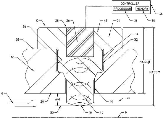
1. A system, comprising:
a well equipment component comprising a first portion that is exposed to an erosive fluid flow during operation of the well equipment component; and
a wear transducer coupled to the well equipment component proximate the first portion, wherein the wear transducer comprises:
a metal coupon including an elongated end that extends into a flowpath of the first portion of the well equipment component such that the elongated end is exposed to the erosive fluid flow;
an ultrasonic sensor coupled to the metal coupon, wherein the ultrasonic sensor transmits ultrasonic signals through the metal coupon toward the elongated end and receives ultrasonic signal reflections back from the elongated end, wherein the ultrasonic sensor comprises:
a transmitting crystal positioned to transmit ultrasonic signals through the metal coupon in a direction of the elongated end;
a receiving crystal positioned to receive ultrasonic signal reflections back from the elongated end of the metal coupon; and
a case housing the transmitting crystal and the receiving crystal; and
a layer of acoustic gel disposed in a space between an end of the case and a surface of the metal coupon.
|