| CPC F04D 29/12 (2013.01) [F04D 29/043 (2013.01); F04D 29/22 (2013.01)] | 7 Claims |

|
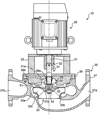
1. A pump comprising:
a rotary shaft,
an impeller that is attached to the rotary shaft and that rotates with rotation of the rotary shaft,
a casing that surrounds the rotary shaft,
a shaft sealing device that seals a gap between the casing and the rotary shaft,
a baffle plate part that is located between the impeller and the shaft sealing device and attached to a rotating body,
the baffle plate part extending in a direction that is inclined or orthogonal with respect to a surface orthogonal to an axial direction of the rotary shaft, and
a rotary baffle plate that is attached to the rotary shaft so as to be located between the impeller and the shaft sealing device,
the rotary baffle plate including a main body part attached to the rotary shaft, and the baffle plate part provided on the main body part,
wherein the main body part includes a curved relief portion near a base of the baffle plate part.
|