| CPC B65D 21/086 (2013.01) [B65D 11/186 (2013.01); B65D 11/1833 (2013.01); B65D 21/0217 (2013.01); B65D 81/3813 (2013.01); E05D 3/12 (2013.01); B29L 2031/712 (2013.01)] | 4 Claims |

|
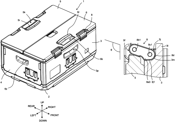
1. A container comprising:
a side wall, an upper hinge member, and an upper wall,
wherein the side wall has a first concave portion,
the upper wall has a second concave portion,
the upper hinge member is located across the first concave portion and the second concave portion,
the upper hinge member has a case, a first projecting shaft, and a second projecting shaft, the upper hinge member and the side wall are connected rotatably around the first projecting shaft,
the upper hinge member and the upper wall are connected rotatably around the second projecting shaft, and
the first and second projecting shafts are parallel, wherein
when the container is in an upright orientation, such that the side wall is disposed parallel to an up-down axis, the container is configured such that the second projecting shaft is always arranged further in an up direction, along the up-down axis, than the projecting shaft,
wherein the case of the upper hinge member comprises a rotation restricting portion configured to restrict rotation of the upper hinge member,
the rotation restricting portion is configured to abut against a lower surface of the first concave portion, so that when the container is in an upright orientation, such that the side wall is disposed parallel to the up-down axis, the second projecting shaft is not arranged further in a down direction, along the up-down axis, than the first projecting shaft,
the case of the upper hinge member comprises a first arc surface having a center that is the first projecting shaft,
the first concave portion is provided with a second arc surface, and
the upper hinge member is configured to maintain contact between the first and second arc surfaces throughout an entire range of rotation of the upper hinge member with respect to the side wall of the container.
|