| CPC B43K 24/04 (2013.01) [B43K 24/082 (2013.01); B43K 24/084 (2013.01); B43K 25/028 (2013.01)] | 12 Claims |

|
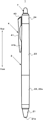
1. A retractable writing instrument, comprising a pen point, a clip, and a barrel, the pen point being configured to be in a state of projecting from the barrel or a state of being retracted into the barrel by sliding the clip in a longitudinal direction of the barrel, wherein
the clip includes a clip body, a holding portion, and a clip base,
the clip body includes one upper wall extending in the longitudinal direction of the barrel and a pair of side walls formed at least on a front side of the upper wall, projecting from both side portions of the upper wall in a direction of a surface of the barrel, and having inner surfaces facing each other,
the holding portion is provided on a back side of the clip body and between the pair of side walls, has a shape capable of producing an elastic force by deformation, and projects more in the direction of the surface of the barrel than the pair of side walls,
the surface of the barrel includes a guide groove extending in the longitudinal direction of the barrel and provided with a pair of side surfaces to restrict lateral movement of the holding portion,
the clip base is connected to a rear side of the clip body and supports the clip body at a height not to cause the pair of side walls to contact the surface of the barrel,
the upper wall of the clip body has a shape with an increasing width from the front side to a rear side,
the pair of side walls of the clip body are formed from a front end to a rear end of the upper wall,
on a rear side of the pair of side walls, a pair of engagement portions are formed projecting inside the clip body,
at a front end of the pair of engagement portions, a pair of stopper walls are formed projecting toward a back surface of the upper wall, and
the pair of engagement portions engage with both sides of the clip base and the pair of stopper walls abut on a front surface of the clip base.
|