| CPC A61B 8/4227 (2013.01) [A61B 7/00 (2013.01); A61B 8/0891 (2013.01); A61B 8/58 (2013.01); A61B 5/02007 (2013.01); A61B 2560/0214 (2013.01)] | 9 Claims |

|
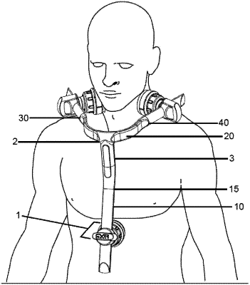
1. An array for determining carotid artery stenosis in a human patient comprising:
a neck having a longitudinal axis;
coupled to the neck is a stem oriented in a first direction away from the longitudinal axis and defining an angle of between 125° and 175° as measured along the longitudinal axis;
a neck vertex coupled to the neck with a pair of arms extending from the neck vertex in the opposite direction to the stem, wherein relative to one another the stem and the arms extend from the neck in opposing directions;
the pair of arms defining an angle of between 225° and 270° as measured from the longitudinal axis of the neck to form a resting state, and wherein each of the stem and arms are made of a flexible material that is configured to be flexed away from the resting state of the flexible material;
wherein the flexible material imparts a force to return back to the resting state; and wherein each of the arms and the stem are configured to receive a sensor pod within a track section and wherein each of the sensor pods comprises:
a housing configured to be coupled to the arms and the stem;
a disposable cap configured to removably attach to the housing;
a diaphragm that extends out of the disposable cap;
a printed circuit board having: integrated circuits, a rechargeable battery, a spring loaded contact, an input, and at least one LED status light;
a piezo element configured to receive vibrations from the diaphragm and output a signal to the input of the printed circuit board; and
a wireless charging coil configured to inductively charge the rechargeable battery.
|