| CPC A47J 43/0722 (2013.01) [A47J 43/085 (2013.01)] | 10 Claims |

|
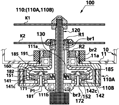
1. A bidirectional simultaneous rotary blade bundle for a mixer, the blade bundle comprising:
a housing (110) having an upper through-hole (111a) and a lower through-hole (111b);
a forward rotary shaft (120) installed through the housing (110) by passing through the upper through-hole (111a) and the lower through-hole (111b) of the housing (110), and connected to a motor shaft of a motor of the mixer and configured to be rotated in a forward direction according to a rotation of the motor shaft;
a forward rotation blade (K1) fixedly provided on an upper side of the forward rotary shaft (120);
a first bearing (br1) axially installed on the forward rotary shaft (120);
a central gear (130) axially installed on the forward rotary shaft (120) and configured to be rotated in the forward direction together with the forward rotary shaft (120);
a plurality of horizontal insertion gears (141, 142, and 143) engaged with the central gear (130), provided at equal intervals to each other, and configured to be rotated in place in a reverse direction according to a rotation of the central gear (130), the reverse direction being opposite to a rotation direction of the central gear (130);
a reverse rotor (160) having inner gear teeth (164) that are formed concentrically with the central gear (130) and are formed in a belt shape along an inner circumferential surface of the reverse rotor (160) in a circumferential direction, the inner gear teeth (164) being engaged with the plurality of horizontal insertion gears (141, 142, and 143) externally, thereby the reverse rotor (160) being configured to be rotated in the reverse direction according to a rotation of the horizontal insertion gears (141, 142, and 143), the reverse direction being same as a rotation direction of the plurality of horizontal insertion gears (141, 142, and 143);
a second bearing (br2) axially installed on the reverse rotor (160) at a position between the reverse rotor (160) and the upper through-hole (111a) of the housing (110); and
a reverse rotation blade (K2) installed on the reverse rotor (160) and configured to be rotated in the reverse direction together with the reverse rotor (160),
wherein the reverse rotor (160) has an inner side in contact with an outer side of the first bearing (br1) and has an outer side in contact with an inner side of the second bearing (br2), so that the reverse rotor (160) is configured to be rotated by being rotatably disposed between the first bearing (br1) and the second bearing (br2), and
between the central gear (130) and the inner gear teeth (164), the plurality of horizontal insertion gears (141, 142, and 143) is simultaneously engaged with both gear teeth (130b) of the central gear (130) and the inner gear teeth (164), and the plurality of horizontal insertion gears (141, 142, and 143) is arranged at equal intervals, so that the plurality of horizontal insertion gears (141, 142, and 143) is configured to be rotated in the reverse direction according to the forward rotation of the central gear (130) and configured to rotate the inner gear teeth (164) in the same direction that is the reverse direction according to the reverse rotation of the plurality of horizontal insertion gears (141, 142, and 143).
|