| CPC H10N 52/01 (2023.02) [G11C 11/161 (2013.01); H10B 61/20 (2023.02); H10N 50/85 (2023.02); H10N 52/00 (2023.02); H10N 52/80 (2023.02); G11C 11/18 (2013.01)] | 12 Claims |
|
1. A three terminal spin-orbit-torque (SOT) switching device, comprising:
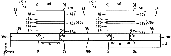
(a) first and second bottom electrodes (BE) that adjoin opposing sidewalls of a dielectric spacer wherein the opposing dielectric spacer sidewalls are separated by a first width (w) along a first axis, and wherein each of the first and second BE have a top surface that is coplanar with a dielectric spacer top surface;
(b) a stack of layers wherein each layer has substantially a second width (w3) along the first axis wherein w3>w, and is the distance between two opposing planar sidewalls aligned parallel to a second axis, and each layer has substantially a first length (d) along the second axis that is orthogonal to the first axis and wherein d is the distance between two opposing planar sidewalls aligned parallel to the first axis, comprising:
(1) a non-magnetic Spin Hall Effect (SHE) layer that adjoins the dielectric spacer top surface and comprised of a Spin Hall Angle (SHA) material, and wherein a bottom end of a first side of the SHE layer contacts the top surface of the first BE and a bottom end of a second side of the SHE layer contacts the top surface of the second BE, and the SHE layer is configured to generate a spin-orbit-torque on an overlying ferromagnetic (FM) layer when a first current is applied across the SHE layer in a first axis direction from the first BE to the second BE, or in a direction opposite to the first axis direction;
(2) the overlying FM layer having a magnetization in a perpendicular-to-plane direction that flips to an opposite direction when the spin-orbit-torque is generated by the SHE layer; and
(3) an uppermost hard mask (HM) layer with a top surface that is formed above the FM layer; and
(c) a top electrode (TE) formed on the HM layer top surface, and configured so that a read operation that determines the magnetization direction in the FM layer is performed when a second current is applied from the TE to one of the first BE and second BE, or from one of the first and second BE to the TE.
|