| CPC H02M 3/1582 (2013.01) [H02M 3/07 (2013.01); H02M 3/158 (2013.01)] | 10 Claims |

|
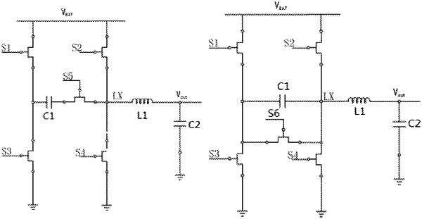
1. A buck-boost circuit, comprising a first switch, a second switch, a third switch, a fourth switch, a fifth switch, a first inductor, a first capacitor, and a second capacitor,
wherein a first terminal of the first switch is connected to an anode of an input power supply; a first terminal of the second switch is connected to the anode of the input power supply; a first terminal of the third switch and a first terminal of the first capacitor are connected to a second terminal of the first switch; a second terminal of the third switch is connected to a cathode of the input power supply; a first terminal of the fourth switch, a second terminal of the first capacitor, and a first terminal of the first inductor are connected to a second terminal of the second switch; a second terminal of the fourth switch is connected to the cathode of the input power supply; a second terminal of the first inductor is connected to an anode of an output power supply; the second capacitor is connected in parallel between the anode and a cathode of the output power supply; and the fifth switch is connected between the second terminal of the first capacitor and the second terminal of the second switch.
|