| CPC H01S 5/06216 (2013.01) [H01S 5/0261 (2013.01); H03K 5/07 (2013.01)] | 19 Claims |

|
1. A pulse generator circuit comprising:
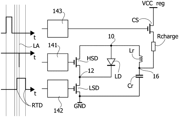
a first node and a second node configured to apply a pulse signal to an electrical load coupled therebetween;
a first electronic switch coupled between the first node and the second node;
a second electronic switch coupled between the second node and a reference node;
an LC resonant circuit comprising a series connection of an inductance and a capacitance having an intermediate node therebetween, the LC resonant circuit coupled between the first node and the reference node;
charge circuitry comprising a further inductance in a current flow line between a supply node and the intermediate node in the LC resonant circuit; and
drive circuitry of the first electronic switch and the second electronic switch, the drive circuitry configured to repeat switching cycles of a sequence of switching cycles comprising:
charge time intervals, wherein the first electronic switch is closed and the second electronic switch is open and the capacitance in the LC resonant circuit is charged via the charge circuit;
wherein the charge circuitry comprises:
a comparator configured to perform a comparison of a charge voltage of the capacitance in the LC resonant circuit with a charge threshold; and
a charge switch arranged in the current flow line intermediate the supply node and the further inductance, the charge switch activatable to couple the further inductance to the supply node as a function of an outcome of the comparison at the comparator.
|