| CPC H01F 27/40 (2013.01) [H01G 4/01 (2013.01); H01G 4/04 (2013.01); H01G 4/258 (2013.01)] | 8 Claims |

|
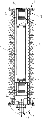
1. A capacitive voltage transformer, comprising: a capacitive voltage-dividing component and an electromagnetic unit, wherein the capacitive voltage-dividing component comprises: one or more levels of stacks, each of the stacks is a coupling capacitor, the coupling capacitor comprises: an upper cover plate, a lower cover plate, an insulating sleeve, and a capacitor core, the upper cover plate, the lower cover plate and the insulating sleeve form an accommodating chamber, the accommodating chamber is a closed chamber filled with dielectric oil, and the capacitor core is impregnated in the dielectric oil, wherein the coupling capacitor further comprises:
squirrel cage electrodes respectively arranged between an upper end surface of the capacitor core and the upper cover plate and between a lower end surface of the capacitor core and the lower cover plate, wherein two squirrel cage electrodes arranged at two ends of the capacitor core are configured to compress the capacitor core between the two squirrel cage electrodes;
volume matching devices arranged in the squirrel cage electrodes and connected to a breathing regulator on the upper cover plate or the lower cover plate, wherein the volume matching devices are configured to compensate for a volume change of the dielectric oil inside;
a high voltage lead arranged in an upper squirrel cage electrode and configured for connecting a high-voltage terminal of the capacitor core to a connection terminal of the upper cover plate; and
a low voltage lead arranged in a lower squirrel cage electrode and configured for connecting a low-voltage terminal of the capacitor core to a connection terminal of the lower cover plate or a low-voltage inner leading-out end of a lead terminal;
a lowermost coupling capacitor is further provided with:
a medium voltage lead arranged in the lower squirrel cage electrode and configured for connecting a middle terminal of the capacitor core to a medium-voltage inner leading-out end of the lead terminal; and
the lead terminal arranged on the lower cover plate, wherein two ends of the lead terminal extend beyond the lower cover plate, and one end of the lead terminal is impregnated in the dielectric oil;
the low voltage lead of the lowermost coupling capacitor is led out through a low-voltage leading-out tube arranged in the lead terminal, and the low-voltage leading-out tube connects the low-voltage inner leading-out end of the lead terminal and a low-voltage outer leading-out end of the lead terminal;
the medium voltage lead of the lowermost coupling capacitor is led out through a medium-voltage leading-out post arranged in the lead terminal, the medium-voltage leading-out post is configured for connecting the medium-voltage inner leading-out end of the lead terminal to a medium-voltage outer leading-out end of the lead terminal, and the medium-voltage leading-out post passes through and out of the low-voltage leading-out tube and is arranged coaxially with the low-voltage leading-out tube.
|