| CPC G06F 30/18 (2020.01) [B60R 16/0207 (2013.01); G06T 17/10 (2013.01); G06F 2113/16 (2020.01)] | 11 Claims |
|
1. A computer based method for an application in a computer aided drafting (CAD) environment for flattening a three dimensional (3D) backshell component to a two dimensional (2D) representation while maintaining a connected wiring component represented in 3D, comprising steps of:
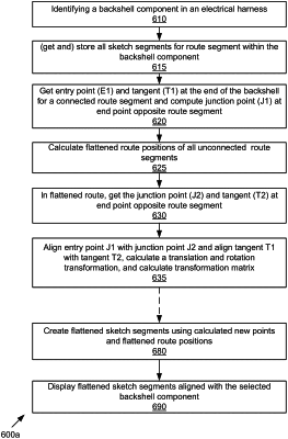
identifying a 3D backshell component comprising a connector, a shell housing, and a connected first route segment comprising a curved route within the shell housing and at least a first sketch segment disposed within the backshell component and/or passing through a backshell component entry point;
storing all sketch segments for the connected first route segment;
identifying a first entry point at a first end point of the connected first route segment;
computing a first tangent at the first entry point;
computing a first junction point (J1) at a connected first route segment second end point using the first tangent and a required segment length;
calculating a flattened route for all route segments unconnected to the backshell component;
identifying a second junction point (J2) in flattened route;
computing a second tangent at the second junction point;
calculating a translation and rotation transformation aligning the first junction point to the second junction point, and aligning the first tangent and the second tangent;
calculating a transformation matrix based on the translation and rotation transformation; and
displaying in 2D the flattened unconnected route segment aligned with the 2D flattened backshell component maintaining the 3D orientation of the 3D route segment with the 3D backshell component,
wherein the flattened unconnected route segment does not intersect the 3D backshell component displayed according to the 3D orientation of the 3D backshell component.
|