| CPC G02B 21/086 (2013.01) [F21V 5/043 (2013.01); G02B 6/0006 (2013.01); G02B 6/0008 (2013.01); G02B 21/367 (2013.01); F21Y 2115/10 (2016.08); G02B 27/30 (2013.01)] | 14 Claims |

|
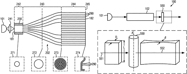
13. A light sheet microscope comprising an optical sensor having an observation direction, an optical device comprising an optical component, and an optical system arranged in a propagation direction of light after an emitting section,
wherein the optical system comprises a cylindrical lens that is adapted to create a light sheet or a set of parallel light sheets from emitted light,
wherein the optical component comprises a receiving section for receiving light from a light source and the emitting section for emitting light, wherein the light source is a non-coherent light source and is adapted to emit light from a two-dimensional region and wherein the optical component is adapted to guide the light from the receiving section to the emitting section such that the light is emitted in a one dimensional pattern at the emitting section,
wherein the optical sensor and the optical device are arranged relative to each other such that the observation direction is in a plane perpendicular to the light sheet and this plane contains the propagation direction of the light sheet, and an angle between the propagation direction and the observation direction is greater than zero, and
wherein the optical component comprises a plurality of multimode fibers or a plurality of single mode fibers for guiding light, wherein, within a tapered section positioned between the receiving section and the emitting section, the plurality of multimode fibers or the plurality of single mode fibers are fused together with one another and tapered at the receiving section into a single fiber comprising a single multimode core and separated at the emitting section into the plurality of multimode fibers or the plurality of single mode fibers, and wherein, within the tapered section, the single fiber comprising the single multimode core at the receiving section smoothly transitions to a bundle of fibers comprising the plurality of single mode fibers or the plurality of single mode fibers at the emitting section, the smooth transition achieved by melting a portion of the bundle of fibers together at one point and increasing a length in a specific portion such that a diameter of the tapered section is reduced from the bundle of fibers to the single fiber comprising the multimode core.
|