| CPC G01R 27/2605 (2013.01) [G01B 7/22 (2013.01)] | 5 Claims |

|
1. An apparatus, comprising:
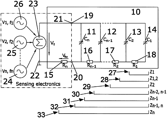
an array of sensors comprising N resistor and capacitor pairs, wherein each resistor and capacitor pair is connected:
in parallel with the capacitor of a preceding N−1 resistor and capacitor pair, and
in series with the resistor of the preceding N−1 resistor and capacitor pair; and
a device operable to measure capacitances and/or resistances in the array of sensors, the device being adapted to connect to the array of sensors over a single physical channel provided by two terminals and being operable to provide at the two terminals an excitation signal for the array of sensors, the excitation signal having N frequency components, and operable on data carrying information on a vector function to determine values of capacitance and/or resistances for the array of sensors, the vector function operable to equate at each of the N frequency components:
a) impedance measured at the two terminals;
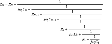
b) an analytical expression approximating the circuit impedance ZN provided in combination by the array of sensors defined as:
 ωi=2πfi where i=1 . . . N, where i=1 . . . N, where C1 is the first capacitance, C2 is the second capacitance, where CN−1 is the N−1th capacitance, Cn is the nth capacitance, R1 is the series resistance of the first capacitance, R2 is the resistance of the second capacitance, RN−1 is the series resistance of the N−1th capacitance, and RN is the series resistance of the Nth capacitance, where w, is the angular frequency of the excitation signal, fi is the frequency of the excitation frequency component applied to the circuit described by the impedance ZN, f1 is the first frequency, f2 is the second frequency, fN−1 is the N−1th frequency, and fN is the Nth frequency.
|