| CPC G01N 3/12 (2013.01) [G01N 33/24 (2013.01)] | 8 Claims |
|
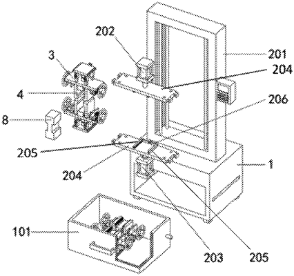
1. A multifunctional rock mechanics tester, consisting of a base (1), a power mechanism (2) is mounted on a top of the base (1), two tension testing mechanisms (3) are arranged on the power mechanism (2) in an up-and-down symmetrical way; a rectangular cavity is set at a lower part of a front end of the base (1) and internally connected with a storage box (101) in a sliding way, two pressure testing mechanisms (6) are placed on a bottom of the storage box (101), a clamping mechanism (7) is set on each pressure testing mechanism (6), two limit components (9) are mounted on the power mechanism (2) in an up-and-down symmetrical way, and a locking component (10) is set on each clamping mechanism (4); each limit component (9) comprises a limit housing (901), a limit slider (902) and a L-shaped pull bar (903), wherein the limit housing (901) is fixedly connected in a middle of a rear end of each of two driving plates (204) and internally connected with the limit slider (902) in a sliding way, a front side angle at a top of the limit slider (902) is rounded, and a bottom of the limit slider (902) is fixedly connected to the L-shaped pull bar (903) that runs through a bottom of the limit housing (901) and sleeved with a spring inside the limit housing (901);
each tension testing mechanism (3) comprises a connecting seat A (301), four first sliding sleeves (302), four first sliding pillars (303), a pull plate (304), a tension sensor (305) and a connector plate A (306), wherein the connecting seat A (301) is connected between two adjacent connecting slides (205) in a sliding way and fixedly connected with the four first sliding sleeves (302) at a top, each first sliding sleeve (302) is internally connected to a corresponding first sliding pillar (303) in a sliding way, the pull plate (304) is fixedly connected with a top of the four first sliding sleeves (302) and provided with two second T chutes, the tension sensor (305) is connected between the connecting seat A (301) and the pull plate (304), the connector plate A (306) is arranged in a middle of a rear of the connecting seat A (301), and a rectangular socket is set on a top of the connector plate A (306);
each pressure testing mechanism (6) comprises a rectangular support plate (601), four second sliding pillars (602), four second sliding sleeves (603), a connecting seat B (604), a connector plate B (605), and a pressure sensor (606), wherein the four second sliding pillars (602) are fixedly connected with a bottom of the rectangular support plate (601), each second sliding sleeve (603) is internally connected with a corresponding second sliding pillar (602) in a sliding way, the connecting seat B (604) is fixedly connected with a bottom of the four second sliding sleeves (603), strip sliders are set on both sides of the connecting seat B (604), the connector plate B (605) is arranged in a front end of the connecting seat B (604), a rectangular socket is set on a top of the connector plate B (605), the pressure sensor (606) is arranged between the rectangular support plate (601) and the connecting seat B (604), and two third T chutes are arranged on the rectangular support plate (601).
|