| CPC G01M 99/002 (2013.01) [F28F 2200/005 (2013.01)] | 4 Claims |

|
1. A heat transfer limit experimental device of a high-temperature heat pipe equipped with a temperature measurement box, comprising:
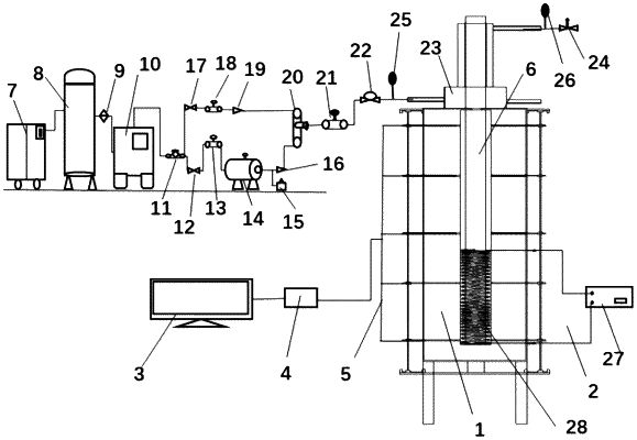
a high-temperature heat pipe (6), an electric heating system (2), a temperature measurement box (1), a control system, a gas-cooled heat exchange system and a data acquisition system; wherein the electric heating system (2) is connected to the high-temperature heat pipe (6);
the temperature measurement box (1) is connected to the gas-cooled heat exchange system; the data acquisition system is connected to the gas-cooled heat exchange system, the temperature measurement box (1), and the electric heating system (2); the control system is connected to the gas-cooled heat exchange system, the temperature measurement box (1), and the electric heating system (2); and the high-temperature heat pipe (6) is disposed inside the temperature measurement box (1);
the temperature measurement box (1) comprises a box body (29), thermal insulation tilling material (30), a conduit (31), step motors (32), a clamp component (33), a fixing plate (34), two slide rails (35), a K-type insulated thermocouple (5), a gas-cooled jacket support plate (36), and a bolt (37); wherein the gas-cooled jacket support plate (36) is disposed on the top of the box body (29); the bolt (37) is fixed to the gas-cooled jacket support plate (36); the thermal insulation filling material (30) is located inside the box body (29); the two slide rails (35) are disposed at an upper end and a lower end of the box body (29) respectively; an end of each slide rail (35) is disposed with one of the step motors (32); the step motors (32) are connected to the fixing plate (34) through screws, and configured to drive the fixing plate (34) to move; an end of the clamp component (33) is horizontally fixed to the fixing plate (34), and configured to clamp and fix an end of the K-type insulated thermocouple (5) by a clamp head (42); the other end of the K-type insulated thermocouple (5) is disposed in the conduit (31); the conduit (31) passes through the box body (29) and terminates at the high-temperature heat pipe (6); and the K-type insulated thermocouple (5) is pushed to move by the fixing plate (34);
the gas-cooled heat exchange system comprises an air compressor (7), a gas storage tank (8), a filter (9), a refrigerant dryer (10), a pressure reducing valve (11), a first shut-off valve (12), a first mass flow controller (13), a gas heater (14), a safety valve (15), a first check valve (16), a second shut-off valve (17), a second mass flow controller (18), a second check valve (19), a gas mixer (20), a differential pressure mass flowmeter (21), a pressure transmitter (22), a gas-cooled jacket (23), and a back pressure control valve (24); wherein, the air compressor (7) is connected to an inlet of the gas storage tank (8); an outlet of the gas storage tank (8) is connected to an inlet of the filter (9); an outlet of the filter (9) is connected to an inlet of the refrigerant dryer (10); an outlet of the refrigerant dryer (10) is connected to an inlet of the pressure reducing valve (11); an outlet of the pressure reducing valve (11) is connected to an inlet of the first shut-off valve (12) and an inlet of the second shut-off valve (17) via a three-way pipe; an outlet of the first shut-off valve (12) is connected to an inlet of the first mass flow controller (13); an outlet of the first mass flow controller (13) is connected to an inlet of the gas heater (14); an outlet of the gas heater (14) is connected to an inlet of the first check valve (16) and the safety valve (15); an outlet of the first check valve (16) is connected to a first inlet of the gas mixer (20); an outlet of the gas mixer (20) is connected to an inlet of the differential pressure mass flowmeter (21); an outlet of the differential pressure mass flowmeter (21) is connected to an inlet of the pressure transmitter (22); an outlet of the pressure transmitter (22) is connected to an inlet of the gas-cooled jacket (23); an outlet of the gas-cooled jacket (23) is connected to the back pressure control valve (24); an outlet of the second shut-off valve (17) is connected to an inlet of the second mass flow controller (18); an outlet of the second mass flow controller (18) is connected to an inlet of the second check valve (19); and an outlet of the second check valve (19) is connected to a second inlet of the gas mixer (20); and
the gas-cooled jacket (23) comprises a threaded hole (41), a first gas-cooled jacket inlet (38), a second gas-cooled jacket inlet (39), and a gas-cooled jacket outlet (40); wherein the gas-cooled jacket (23) is disposed outside the high-temperature heat pipe (6); the gas-cooled jacket (23) is fixed to the gas-cooled jacket support plate (36) by a nut after the bolt (37) passes through the threaded hole (41); the first gas-cooled jacket inlet (38) is disposed on a side of the bottom the gas-cooled jacket (23); the second gas-cooled jacket inlet (39) is disposed on the other side of the bottom of the gas-cooled jacket (23); and the gas-cooled jacket outlet (40) is disposed at the top of the gas-cooled jacket (23).
|