| CPC F28F 1/025 (2013.01) [H01L 23/427 (2013.01); F28F 2250/00 (2013.01); H01L 23/4006 (2013.01); H01L 2023/4087 (2013.01)] | 5 Claims |

|
1. A cooling device comprising:
a container in which a refrigerant is sealed;
an evaporating part that evaporates the refrigerant in a liquid phase by heat reception inside the container to generate the refrigerant in a gas phase;
a moving region provided along an upper surface of the container and in which the refrigerant in the liquid phase moves;
a condensing part provided in the moving region and that condenses the refrigerant in the gas phase by heat dissipation inside the container to generate the refrigerant in the liquid phase; and
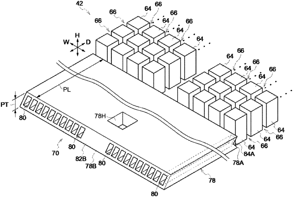
a plate-shaped or block-shaped flow path member provided between a lower surface of the container and the moving region and in which a plurality of flow paths configured to transport the refrigerant in a liquid phase from the condensing part to the evaporating part by surface tension inside the container is formed in parallel,
the evaporating part evaporates the refrigerant in the liquid phase, which is transported from the plate-shaped or block-shaped flow path, in column members which extend from the lower surface of the container to the upper surface of the container.
|