| CPC F23R 3/283 (2013.01) [F02C 7/24 (2013.01); F23R 3/286 (2013.01); F05D 2260/231 (2013.01)] | 16 Claims |
|
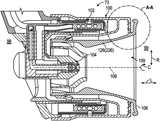
1. A heat shield for a fuel nozzle of a gas turbine combustor, the heat shield defining a radial direction, a longitudinal direction along a centerline axis, and a circumferential direction about the centerline axis, the heat shield comprising:
a radial flange extending in the radial direction and the circumferential direction, the radial flange having a fuel nozzle opening extending therethrough at a radially inward end of the radial flange; and
an annular conical wall extending in the longitudinal direction and the circumferential direction, the annular conical wall forming a connection to the radial flange at the radially inward end of the radial flange,
wherein, the radial flange includes a flange forward side with a flange forward face, and a flange aft side with a flange aft face, and
wherein the radial flange further comprises (a) a flange inner portion extending radially outward from the radially inward end of the radial flange to an outer end of the flange inner portion, the flange inner portion extending longitudinally between a part of the flange forward face and a part of the flange aft face where both the part of the flange forward face and the part of the flange aft face extend radially to the outer end of the flange inner portion and both are parallel to the radial direction, the outer end of the flange inner portion being arranged radially outward of the connection of the annular conical wall and the radially inward end of the radial flange, (b) a flange angled portion extending at an angle radially outward and longitudinally aft from the outer end of the flange inner portion to an outer end of the flange angled portion, and (c) a flange outer end portion arranged at the outer end of the flange angled portion, wherein the flange outer end portion includes a flange rounded end portion on one of the flange forward side or the flange aft side, and a flange rounded protruding lip on the other of the flange forward side or the flange aft side, the flange rounded protruding lip extending in the longitudinal direction.
|