| CPC F17C 1/06 (2013.01) [F17C 2201/0138 (2013.01); F17C 2203/0604 (2013.01); F17C 2203/066 (2013.01); F17C 2203/0619 (2013.01); F17C 2203/0663 (2013.01); F17C 2205/0305 (2013.01); F17C 2205/0326 (2013.01); F17C 2205/0332 (2013.01); F17C 2205/0335 (2013.01); F17C 2205/0341 (2013.01); F17C 2205/0397 (2013.01); F17C 2221/012 (2013.01); F17C 2221/014 (2013.01); F17C 2221/017 (2013.01); F17C 2221/033 (2013.01); F17C 2221/035 (2013.01); F17C 2223/0123 (2013.01); F17C 2223/036 (2013.01); F17C 2227/0114 (2013.01); F17C 2227/0344 (2013.01); F17C 2250/0439 (2013.01); F17C 2265/066 (2013.01); F17C 2270/0168 (2013.01)] | 15 Claims |

|
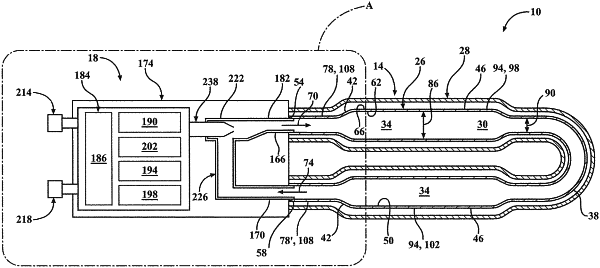
1. A pressure vessel comprising:
an elongated folded tank having an interior for storage of fluid, said tank including a polymeric liner defined by an elongated cylindrical wall extending between a first tank end and a second tank end, said liner having a plurality of chambers for storage of fluid, said plurality of chambers including at least a first chamber adjacent said first tank end and a last chamber adjacent said second tank end, said liner surrounded by an outer composite shell of resin and fiber, and said elongated folded tank folded into a predetermined stacking architecture such that said first tank end is adjacent said second tank end; and
a valve assembly coupled to said elongated folded tank, said valve assembly comprising:
a first filling coupler operatively coupled to said first tank end;
a second filling coupler operatively coupled to said second tank end;
a mixing chamber, said mixing chamber communicating with said first filling coupler to introduce fluid to said first tank end and into said interior of said tank;
at least one Venturi nozzle configured to introduce a first flow of fluid from an external fluid source to said mixing chamber;
a suction line communicating with said second filling coupler and coupled to said mixing chamber such that when a second flow of fluid originates from said second end of said tank, said second flow of fluid flows into said mixing chamber and is mixed with said first flow of fluid within said mixing chamber;
a third filling coupler for selectively coupling said valve assembly to an external fluid source for receiving said first flow of fluid from said external fluid source, said third filling coupler selectively coupled to said Venturi nozzle; and
said valve assembly includes a fourth filling coupler for selectively coupling said valve assembly to a temperature pressure relief device (TPRD) vent.
|