| CPC F16B 7/042 (2013.01) [B64C 25/34 (2013.01); F16D 1/02 (2013.01); F16D 1/06 (2013.01)] | 21 Claims |

|
1. A method of manufacturing a composite beam structure,
wherein the composite beam structure comprises:
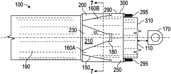
an end piece having an axis, an end piece outer periphery surface, and an end piece mating end defining an end piece axial boundary,
wherein the end piece has an outwardly facing surface that is continuous about its perimeter in a circumferential direction, wherein wedge-shaped inner locking features extend radially outward from said outwardly facing surface, wherein the wedge-shaped inner locking features that are formed at the end piece mating end and are spaced apart from one another in the circumferential direction;
wherein, in the hoop direction along the end piece axial boundary, the end piece is continuous about its perimeter between the wedge-shaped inner locking features; and
a composite tube configured to surround at least a portion of the end piece mating end to form a beam joint,
wherein wedge-shaped imprints are formed through the composite tube, corresponding to the wedge-shaped inner locking features,
wherein the wedge-shaped imprints define respective composite tube wedge-shaped depression surfaces about a composite tube inner periphery and composite tube wedge-shaped boss surfaces about a composite tube outer periphery, and
wherein the wedge-shaped inner locking features of the end piece are covered by the composite tube wedge-shaped depression surfaces,
wherein:
each of the wedge-shaped inner locking features is triangular having a vertex surface portion that is disposed along the axis and is directed away from the end piece axial boundary at the end piece mating end;
each of the wedge-shaped inner locking features is configured as an isosceles triangle, oriented such that it is bisected by the axis to define first and second triangular surfaces, the method comprising:
positioning the end piece on the mandrel, wherein the end piece has the axis, the end piece outer periphery surface, and the end piece mating end, wherein the end piece includes the wedge-shaped inner locking features that are formed to project outwardly from the end piece outer periphery surface at the end piece mating end and are spaced apart from one another; and
positioning the composite tube on the mandrel so that the composite tube surrounds at least the portion of the end piece mating end to form the beam joint;
clamping the composite tube against the end piece mating end to form the wedge-shaped imprints through the composite tube, corresponding to the wedge-shaped inner locking features on the end piece mating end, wherein the wedge-shaped imprints respectively define the composite tube wedge-shaped depression surfaces about the composite tube inner periphery and composite tube wedge-shaped boss surfaces about the composite tube outer periphery, and wherein the wedge-shaped inner locking features of the end piece are covered by the composite tube wedge-shaped depression surfaces; and
removing the composite beam structure and the mandrel from one another upon curing for thermoset or solidifying for thermoplastic composite materials, respectively.
|