| CPC F02C 7/18 (2013.01) [F02C 6/00 (2013.01); F05D 2220/76 (2013.01)] | 14 Claims |

|
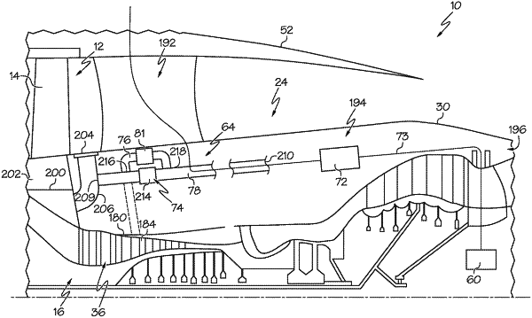
1. A gas turbine engine comprising:
a fan located at a forward portion of the gas turbine engine;
a compressor section and a turbine section arranged in serial flow order, the compressor section and the turbine section together defining a core airflow path;
a rotary member rotatable with at least a portion of the compressor section and with at least a portion of the turbine section;
an electrical machine coupled to the rotary member and located at least partially inward of the core airflow path in a radial direction;
an enclosure that at least partially encloses the electrical machine, the enclosure at least partially defining a first cooling airflow path within the enclosure that at least partially defines a first cooling airflow buffer cavity at least partially around the electrical machine, the first cooling airflow path in communication with a second cooling airflow path located outside the enclosure that at least partially defines a second cooling airflow buffer cavity at least partially around the enclosure; and
a cooling duct that is configured to direct pressurized air past the electrical machine in the radial direction and then into the enclosure, wherein the pressurized air is directed along both the first cooling airflow path and the second cooling airflow path providing the pressurized air to the first cooling airflow buffer cavity and the second cooling airflow buffer cavity.
|