| CPC E05B 65/108 (2013.01) [E05B 17/22 (2013.01); E05B 41/00 (2013.01); E05B 47/0001 (2013.01); E05B 63/246 (2013.01); E05B 65/06 (2013.01); E05B 65/1013 (2013.01); E05B 65/1053 (2013.01); E05B 65/1093 (2013.01); E05B 81/77 (2013.01); E05C 19/166 (2013.01); G01R 15/202 (2013.01); G07C 9/00309 (2013.01); E05B 17/0083 (2013.01); E05B 39/04 (2013.01); E05B 47/0012 (2013.01); E05B 47/0615 (2013.01); E05B 2045/067 (2013.01); E05B 2045/0625 (2013.01); E05B 2045/0655 (2013.01); E05B 2047/0014 (2013.01); E05B 2047/0067 (2013.01); E05B 2047/0069 (2013.01); E05B 2047/0089 (2013.01); E05Y 2400/44 (2013.01); G08B 13/06 (2013.01); G08B 13/08 (2013.01); G08B 25/10 (2013.01); Y10T 292/0908 (2015.04)] | 20 Claims |
|
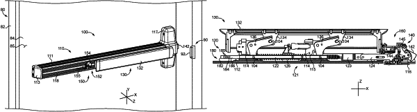
1. A retrofit kit for an exit device comprising a mounting assembly, a drive assembly, and a latchbolt assembly; wherein the mounting assembly includes a channel member, a header plate, and a header bracket mounted to the header plate; wherein the drive assembly is movably mounted to the mounting assembly and includes a manually-operable pushbar; and wherein the latchbolt assembly is operably connected with the drive assembly and includes a latchbolt movably mounted to the header bracket; the retrofit kit comprising:
a conduit configured to be positioned in the channel member, the conduit including a coupling feature configured to engage a corresponding coupling feature of the mounting assembly;
a wire harness including a first plurality of wires, a first wire harness connector, and a second wire harness connector in communication with the first wire harness connector via the first plurality of wires, wherein the first plurality of wires is configured to be received in the conduit and to extend through a length of the conduit;
a header sensor assembly comprising:
a base plate including an opening and a positioning flange, wherein the positioning flange is configured to engage one of an edge or a sidewall of the header bracket to aid in positioning of the base plate;
a first mounting device operable to couple the base plate with the header bracket;
a latchbolt position sensor movably mounted to the base plate, wherein the latchbolt position sensor is operable to transmit latchbolt position signals in response to movement of a component of the latchbolt assembly relative to a sensing region of the latchbolt position sensor, wherein the sensing region is aligned with the opening of the base plate;
a first coupling device operable to selectively retain the latchbolt position sensor in each of a plurality of positions relative to the base plate; and
a first mating connector in communication with the latchbolt position sensor, wherein the first mating connector is configured to matingly engage the first wire harness connector to electrically connect the first plurality of wires and the latchbolt position sensor; and
a control assembly comprising:
a housing including a first set of rails operable to slidably engage a first set of passages formed in the channel member;
a controller mounted to the housing; and
a second mating connector in communication with the controller, wherein the second mating connector is configured to matingly engage the second wire harness connector to electrically connect the first plurality of wires and the controller; and
wherein the controller is operable to determine an extended/retracted position of the latchbolt based at least in part upon latchbolt position signals received from the latchbolt position sensor.
|