| CPC C23C 18/1628 (2013.01) [B01F 35/325 (2022.01); B05C 3/02 (2013.01); B05C 3/04 (2013.01); C23C 18/1683 (2013.01); C25D 17/00 (2013.01); C25D 17/02 (2013.01); C25D 21/10 (2013.01)] | 6 Claims |

|
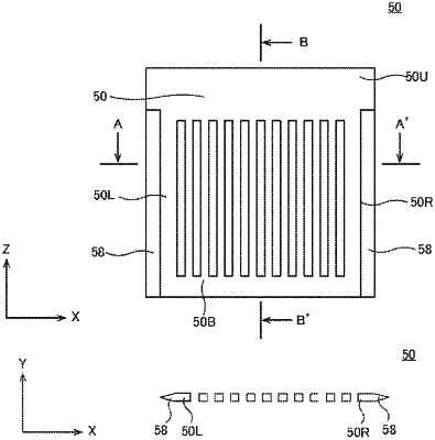
1. A surface treatment device comprising at least one paddle in a plate shape, in a surface treatment tank, for stirring a surface treatment solution near a substrate by reciprocally moving the paddle with respect to the substrate, wherein the paddle includes a plurality of square bars provided in a depth direction or a horizontal direction of the surface treatment solution and said plurality of square bars provided at regular intervals along the substrate, said plurality of square bars being integrally formed in the paddle, and a structure with a tapered or circular cross-section for decreasing a generation of turbulent flow while mixing a liquid is arranged on at least one side of an end of the paddle, wherein the square bars are located in a central region of the paddle to reduce vibration in the paddle and provide uniform stirring of the surface treatment solution, and wherein the structure is located in a region of the paddle that is outside of the central region; wherein a shape of the structure is a tapered shape or a circular shape in a cross section in a thickness direction of the structure; wherein each square bar of the plurality of square bars is provided with a curved surface with respect to the substrate in a cross section in a thickness direction of the plurality of square bars, and the curved surface is provided alternately facing left and facing right with respect to the substrate;
wherein each square bar of the plurality of square bars comprises a side of 5 to 10 mm in length; and wherein each square bar of the plurality of square bars includes a curved surface having a radius of 3 to 10 mm.
|