| CPC B64D 33/08 (2013.01) [B64C 27/26 (2013.01); B64D 27/24 (2013.01)] | 18 Claims |

|
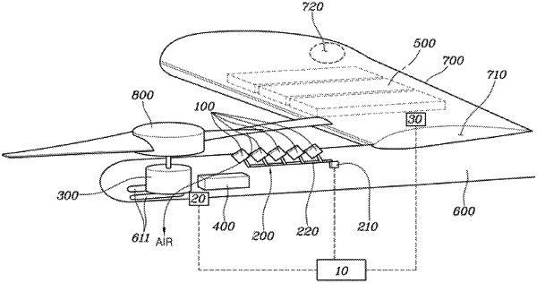
1. An air mobility vehicle with a cooling air system, the air mobility vehicle comprising:
rotary wings mounted on an outside of the air mobility vehicle;
a motor disposed at an inside of the air mobility vehicle;
an inverter disposed at the inside of the air mobility vehicle;
at least a battery disposed at the inside of the air mobility vehicle;
at least an air flap located under a mounting position of each of the rotary wings and rotatably mounted inside at least an opening provided in the air mobility vehicle to guide a flow direction of air flowing to a region under each of the rotary wings to the inside of the air mobility vehicle;
an actuator coupled to the at least an air flap and configured to rotate the at least an air flap to selectively guide the air having passed through the at least an air flap to the motor and the inverter, or to the at least a battery; and
a controller electrically connected to the actuator and configured to control a flow of the air having passed through the at least an air flap by controlling the actuator according to a driving state of the air mobility vehicle or temperatures of the motor, the inverter, and the at least a battery.
|