| CPC B64C 3/58 (2013.01) [B64C 1/06 (2013.01); B64C 1/26 (2013.01); B64F 5/10 (2017.01)] | 6 Claims |

|
1. An aircraft structural assembly comprising:
a fuselage portion partially defining a pressure vessel containing a passenger cabin including a cabin floor, the fuselage portion comprising one or more fuselage frames and a fuselage skin supported by the one or more fuselage frames; and
a wing unit attached to the fuselage portion the wing unit comprising:
a first wing extending in a first lateral direction relative to the fuselage portion and a second wing extending in an opposite second lateral direction relative to the fuselage portion;
a first pressure fence attached to the first wing, the first pressure fence defining a first part of the pressure vessel partially defined by the fuselage portion, the first pressure fence being attached to the fuselage portion at a first joining location that is disposed vertically above the cabin floor; and
a second pressure fence attached to the second wing, the second pressure fence defining a second part of the pressure vessel partially defined by the fuselage portion,
the second pressure fence being attached to the fuselage portion at a second joining location that is disposed vertically above the cabin floor,
wherein:
the first pressure fence comprises a first fence skin and the second pressure fence comprises a second fence skin;
the first fence skin extends upwardly relative to an upper wing skin of the first wing and also in the first lateral direction;
the second fence skin extends upwardly relative to the upper wing skin of the second wing and also in the second lateral direction;
an upper portion of the first fence skin is attached to a first stringer of the fuselage portion and an upper portion of the second fence skin is attached to a second stringer of the fuselage portion;
the first and second stringers are disposed vertically above the cabin floor of the fuselage portion;
the first and second stringers and the first and second fence skins extend along a longitudinal axis of the fuselage portion; and
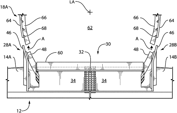
the first pressure fence and the second pressure fence cooperatively define a cradle into which part of the fuselage portion is received, wherein:
a first surface of the upper portion of the first fence skin abuts a portion of a surface of the fuselage skin in a first contact area;
a portion of a second surface of the upper portion of the first fence skin abuts a portion of a surface of a fuselage frame from the one or more fuselage frames in a second contact area, the second contact area being at an angle from the first contact area; and
the upper portion of the first fence skin protrudes upward to guide the fuselage frame for self-alignment in the first or second lateral direction between the fuselage portion and the first pressure fence upon being brought together.
|