| CPC B60L 7/24 (2013.01) [B60L 15/2009 (2013.01); B60L 50/60 (2019.02); G01R 19/16576 (2013.01); B60L 2200/18 (2013.01); B60L 2200/28 (2013.01); B60L 2210/10 (2013.01); B60L 2240/423 (2013.01); B60L 2240/527 (2013.01)] | 14 Claims |

|
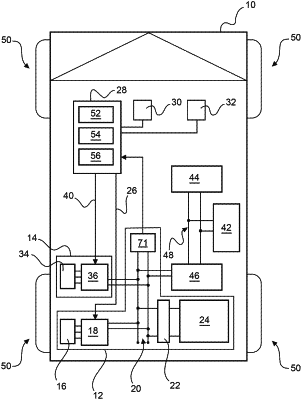
1. A control unit (56) for a vehicle (10) having an electric drive (12) and an electromechanically actuated brake unit (14), wherein the electric drive (12) includes a high-voltage DC link (20) disconnectably connected to a first energy store (24) of the electric drive (12), a converter (18) connected to the high-voltage DC link (20) and operable bidirectionally, and an electric drive motor (16) connected to the converter (18) for driving a wheel (50) of the vehicle (10), the electric motor being operable in a generator mode, wherein the electromechanically actuated brake unit (14) includes a brake drive circuit (36) connected to the high-voltage DC link (20), and an electric brake motor (34) connected to the brake drive circuit (36), for actuating a brake of the vehicle (10),
wherein the control unit comprises a function block (55), which includes:
an input (69) for receiving a voltage signal (68) indicative of the voltage of the high-voltage DC link (20),
a first output (63) for outputting a converter drive signal (60) for driving the converter (18), and
a first closed-loop controller unit (66) for generating the converter drive signal (60) depending on the received voltage signal (68) and a predefined comparison value (70), in particular a setpoint voltage value.
|