US 11,890,862 B2
Image recording device having a compact form factor
Tetsuo Asada, Kuwana (JP); Hirotaka Aoki, Nagoya (JP); Satoru Nakakita, Nagoya (JP); Shota Iijima, Nagoya (JP); Kenji Samoto, Nagoya (JP); and Yuji Koga, Nagoya (JP)
Assigned to Brother Kogyo Kabushiki Kaisha, Nagoya (JP)
Filed by BROTHER KOGYO KABUSHIKI KAISHA, Nagoya (JP)
Filed on Jul. 20, 2021, as Appl. No. 17/380,480.
Application 17/380,480 is a continuation of application No. 16/544,340, filed on Aug. 19, 2019, granted, now 11,077,678.
Application 16/544,340 is a continuation of application No. 16/134,477, filed on Sep. 18, 2018, granted, now 10,414,174, issued on Sep. 17, 2019.
Application 16/134,477 is a continuation of application No. 15/276,206, filed on Sep. 26, 2016, granted, now 10,086,629, issued on Oct. 2, 2018.
Application 15/276,206 is a continuation of application No. 14/949,251, filed on Nov. 23, 2015, granted, now 9,452,619, issued on Sep. 27, 2016.
Application 14/949,251 is a continuation of application No. 14/727,290, filed on Jun. 1, 2015, granted, now 9,283,778, issued on Mar. 15, 2016.
Application 14/727,290 is a continuation of application No. 14/319,413, filed on Jun. 30, 2014, granted, now 9,045,302, issued on Jun. 2, 2015.
Application 14/319,413 is a continuation of application No. 12/892,390, filed on Sep. 28, 2010, granted, now 8,768,235, issued on Jul. 1, 2014.
Claims priority of application No. 2009-299236 (JP), filed on Dec. 29, 2009; and application No. 2009-299273 (JP), filed on Dec. 29, 2009.
Prior Publication US 2022/0040995 A1, Feb. 10, 2022
This patent is subject to a terminal disclaimer.
Int. Cl. B41J 11/00 (2006.01); B41J 13/10 (2006.01); B41J 3/60 (2006.01); B41J 13/00 (2006.01); B41J 29/02 (2006.01); B65H 3/06 (2006.01); B65H 5/26 (2006.01); B65H 1/08 (2006.01); B41J 11/58 (2006.01)
CPC B41J 11/0045 (2013.01) [B41J 3/60 (2013.01); B41J 11/58 (2013.01); B41J 13/0045 (2013.01); B41J 13/103 (2013.01); B41J 29/023 (2013.01); B65H 1/08 (2013.01); B65H 3/0684 (2013.01); B65H 5/26 (2013.01); B65H 2404/1521 (2013.01); B65H 2405/1136 (2013.01); B65H 2405/31 (2013.01); G03G 2215/004 (2013.01); G03G 2215/00396 (2013.01)] 9 Claims
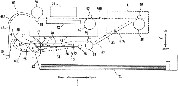
OG exemplary drawing
 
1. An image recording device comprising:
a tray configured to hold a sheet thereon;
a sheet feeder configured to feed the sheet on the tray, the sheet feeder comprising an arm and a roller rotatably supported by the arm, the arm being configured to pivot about a pivot axis such that the roller moves between a first roller position and a second roller position which is above the first roller position;
a recording unit configured to record an image on the sheet fed by the roller of the sheet feeder; and
a return guide comprising an upper surface, a lower surface opposite to the upper surface, and a cover member, the upper surface being configured to guide the sheet having the image recorded thereon back toward the recording unit in a return direction, where the pivot axis of the sheet feeder is located between a portion of the upper surface of the return guide and the tray, and
wherein the arm includes a portion configured to contact the lower surface of the return guide to prevent the roller from colliding with the return guide other than the cover member.