| CPC B23C 5/2472 (2013.01) [B23C 5/08 (2013.01); B23C 5/2234 (2013.01); B23C 2200/0455 (2013.01); B23C 2200/367 (2013.01); B23C 2210/02 (2013.01); B23C 2210/246 (2013.01)] | 21 Claims |
|
1. A rotary cutting tool (20) rotatable about a tool axis (AT) in a direction of rotation (RD),
the tool axis (AT) defining a forward-to-rearward direction (DF, DR), and comprising:
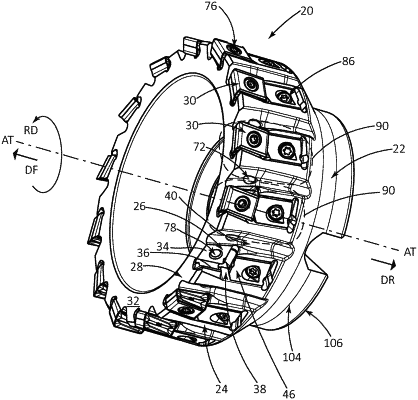
a cutting body (22) having a forward envelope surface (24) and at least one insert receiving pocket (26) formed in the forward envelope surface (24), the insert receiving pocket (26) opening out at a forward body end (28) of the cutting body (22) and having a cutting insert (30) removably secured therein,
the forward envelope surface (24) also having an adjustment recess (38) located axially rearward of the insert receiving pocket (26),
the adjustment recess (38) including a radially outward facing recess side surface (44) and an adjustment tongue (46) extending axially rearwardly from a tongue root (48) to a tongue tip (50),
the adjustment tongue (46) being spaced apart from the recess side surface (44) by a first inner passage (54), and the tongue root (48) having a shoulder surface (56) facing in the forward direction (DF) and a pivot axis (AP), and
the adjustment tongue (46) also having opposing radially inner and radially outer tongue side surfaces (80, 82), and a tongue through bore (84) extending therebetween intersecting the radially inner and radially outer tongue side surfaces (80, 82),
wherein:
the cutting insert (30) is in clamping contact with the shoulder surface (56);
an adjustment screw (86) having an adjustment axis (AA) extends through the tongue through bore (84), traverses the first inner passage (54), and engages the recess side surface (44); and
rotation of the adjustment screw (86) in a first adjustment direction (DA1) about the adjustment axis (AA) causes rotational displacement of the adjustment tongue (46) about the pivot axis (AP) and axial displacement of the cutting insert (30) in the forward direction (DF),
and wherein:
in a cross-section of the cutting tool (20) taken in a radial plane (PR) containing the tool axis (AT) and intersecting the adjustment tongue (46), the first inner passage (54) has an imaginary first straight line (L1) disposed between the recess side surface (44) and the tongue's radially inner side surface (80), and the imaginary first straight line (L1) intersects a recess rear end surface (88) located axially rearward of the tongue's radially inner side surface (80),
the recess rear end surface (88) is formed on a first body sub-portion (90) of the cutting body (22), and
the adjustment tongue (46) is integrally formed with the first body sub-portion (90) to have unitary one-piece construction therewith.
|