| CPC B22F 3/115 (2013.01) [B22D 23/003 (2013.01); B22F 10/22 (2021.01); B22F 12/13 (2021.01); B22F 12/38 (2021.01); B22F 12/50 (2021.01); B22F 12/53 (2021.01); B33Y 30/00 (2014.12)] | 5 Claims |

|
1. A printhead (1) for a 3D printer, the printhead (1) comprising:
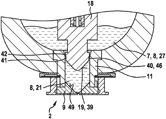
a piston (5) for a printhead (1) of a 3D printer, the piston (5) comprising a piston rod (17) and a plunger (18) connected to the piston rod (17), wherein the plunger (18) has a pressure side (19), which has a surface (39) that is convex or tapers to a point,
a housing (3);
a device (28) for supplying a metal (14);
a reservoir (7, 27) for a liquid phase (8) of the metal (14); and
a nozzle device (2) having a guide sleeve (11) and a nozzle plate (9),
wherein the plunger (18), the guide sleeve (11) and the nozzle plate (9) form a displacement space (21), wherein the plunger (18) and the guide sleeve (11) form at least one region (40) for conducting the liquid phase (8) between the reservoir (27) and the displacement space (21),
wherein the region (40) has a gap (46) for a discharge of gas inclusions from the displacement space (21) into the reservoir (7, 27), and
wherein the gap (46) is formed as an annular gap in a first plane (41) arranged on the pressure side (19) of the plunger (18) and is formed as at least one axial recess in a second plane (42).
|