| CPC B07C 3/06 (2013.01) [B07C 3/008 (2013.01); B64F 1/368 (2013.01); B65G 47/24 (2013.01); B65G 65/32 (2013.01)] | 7 Claims |

|
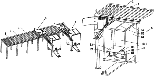
1. An automatic baggage-packing device for urban terminals based on artificial intelligence, comprising:
a baggage transfer rack including:
transfer sticks that form a baggage transfer channel,
a plurality of selectors located above the baggage transfer channel, wherein the selectors are arranged in turn in an extension direction of the baggage transfer channel; and
an automatic loading device set outside the baggage transfer rack to cooperate with the selectors to load selected baggage,
wherein each of the plurality of selectors comprises:
a pair of arc guide plates,
a pair of limit plates,
a pair of connecting rods,
a regulating device, and
a driving cylinder, wherein the pair of arc guide plates are symmetrically installed above the baggage transfer channel, and a side of each arc guide plate which is near the upper end of the baggage transfer channel extends away from each other to form a guide surface; each limit plate is fixedly installed at one end of a corresponding arc guide plate away from the guide surface end, the arc guide plates and the limit plates cooperate with each other to form a clamping area configured to clamp baggage; each connecting rod is fixedly installed below the limit plates and extends downward through the baggage transfer channel, the baggage transfer channel is provided with a moving area for moving each connecting rod, the regulating device is arranged between an end of one of the connecting rod that extends away from the limit plates and the baggage transfer rack, and the driving cylinder is installed between the baggage transfer rack and the regulating device to drive the regulating device to move;
wherein a side wall of the baggage transfer rack comprises a conveying device that cooperates with the automatic loading device to transport baggage in the clamping area to the automatic loading device;
wherein the regulating device comprises:
a sliding plate,
a plurality of hinged rods,
a pair of limiting rods,
a driving tension spring,
a telescopic frame, and
a first pressing switch, wherein the sliding plate is installed on the baggage transfer rack, each connecting rod is installed on an upper surface of the sliding plate, there is a sliding groove on the sliding plate for the connecting rods to slide through, each hinged rod is symmetrically and rotatably attached on a side and near a bottom of each connecting rod, each limiting rod is installed on the sliding plate and extends upward to the two connecting rods, each hinged rod is set on one of the limiting rods at an end of each hinged rod that extends away from of the connecting rod it respectively attached to, the driving tension spring is arranged between the pair of connecting rods to drive the pair connecting rods to drive them to move closer to each other, the telescopic frame is fixed on an outside of one of the connecting rods and extends in a direction towards the side wall of the baggage transfer rack, the first pressing switch is set at a distal end of the telescopic frame and controls the transfer sticks to stop rotating and the driving cylinder to open and extend.
|