| CPC A61B 17/32 (2013.01) [A61B 17/068 (2013.01); A61B 17/07207 (2013.01); A61B 17/105 (2013.01); A61B 17/320016 (2013.01); A61B 34/76 (2016.02); A61B 2017/00398 (2013.01); A61B 2017/00734 (2013.01)] | 20 Claims |

|
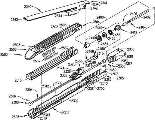
1. A surgical stapling instrument, comprising:
an elongate shaft;
an articulation joint;
an end effector pivotally coupled to said elongate shaft at said articulation joint, wherein said end effector comprises:
a channel; and
an anvil pivotally coupled to said channel, wherein said anvil is movable relative to said channel between an open position and a closed position;
a staple cartridge replaceably seated in said channel, wherein said staple cartridge comprises:
a cartridge body, comprising:
a deck, comprising:
a first anvil-facing surface comprising a plurality of staple cavities defined therein; and
a second anvil-facing surface stepped relative to said first anvil-facing surface;
a plurality of staples movably positioned in said plurality of staple cavities;
a sled assembly, comprising:
a plurality of distal-facing camming ramps; and
a knife; and
a pan attached to said cartridge body, wherein said pan comprises:
a first lateral sidewall comprising a first plurality of windows;
a second lateral sidewall comprising a second plurality of windows; and
a base extending between said first lateral sidewall and said second lateral sidewall, wherein said base comprises a pan slot defined therein;
a drive screw extending longitudinally within said channel, wherein said drive screw comprises a distal end; and
a bearing, wherein said distal end of said drive screw is received by said bearing, wherein said bearing permits said drive screw to freely rotate with respect to said channel, and wherein a rotation of said drive screw in a first direction causes said sled assembly to translate distally through said channel.
|