| CPC H04R 9/047 (2013.01) [H04R 7/04 (2013.01); H04R 9/043 (2013.01); H04R 2209/027 (2013.01); H04R 2499/11 (2013.01)] | 19 Claims |

|
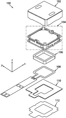
1. An actuator module, comprising:
a base plate extending in a plane;
a voice coil connected to the base plate, the voice coil defining a coil axis perpendicular to the plane;
a magnet assembly comprising:
a back side facing the base plate and a front side facing away from the base plate,
a base layer and sidewalls defining a cup,
an inner element comprising a center magnet mounted within the cup, and
a back plate extending parallel to the plane,
wherein:
the sidewalls comprise a first pair of sidewalls on opposing sides of the cup and a second pair of sidewalls on opposing sides of the cup and adjacent to the first pair of sidewalls, the sidewalls and inner element being separated by an air gap, and
an inner surface of the sidewalls or the inner element of the magnet assembly defines a first quadrilateral shape, and the voice coil defines a second quadrilateral shape, corners of both the first and second quadrilateral shapes being concentric;
a rigid frame attached to the base plate, the rigid frame comprising four stubs each facing a corresponding one of the sidewalls; and
a plurality of springs suspending the magnet assembly relative to the frame and base plate so that the voice coil extends into the air gap,
the plurality of springs comprising a first spring attached to the frame at a first pair of the four stubs respectively facing the first pair of sidewalls and attached to the magnet assembly at the second pair of sidewalls on the front side of the magnet assembly,
the plurality of springs comprising a second spring attached to the frame at a second pair of the four stubs respectively facing the second pair of sidewalls and attached to the magnet assembly at the first pair of sidewalls on the back side of the magnet assembly.
|