| CPC H03M 1/34 (2013.01) [G06F 1/04 (2013.01); G06F 7/501 (2013.01); H03M 1/14 (2013.01); G06F 1/0321 (2013.01); H03M 1/56 (2013.01); H04N 25/75 (2023.01); H04N 25/772 (2023.01)] | 8 Claims |

|
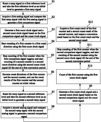
1. An analog-to-digital conversion method, comprising:
in a first conversion period:
resetting a ramp signal to a first reference level and taking the first reference level as an initial level to generate a first ramp signal;
acquiring a first analog signal and comparing the first ramp signal with the first analog signal to generate a first comparison signal;
acquiring a count clock signal and generating a first count clock signal and a second count clock signal based on the first comparison signal and the count clock signal;
starting counting of a first counter in a first count direction using the first count clock signal; and
stopping counting of the first counter when the first comparison signal toggles, and starting counting of a second counter in a second count direction using the second count clock signal till end of the first conversion period; and in a second conversion period:
reversing count directions of the first counter and the second counter, respectively, and using a first count result of the first counter and a second count result of the second counter as initial values;
resetting the ramp signal to a second reference level and taking the second reference level as an initial level to generate a second ramp signal;
acquiring a second analog signal and comparing the second ramp signal with the second analog signal to generate a second comparison signal;
generating a third count clock signal and a fourth count clock signal based on the second comparison signal and the count clock signal;
starting counting of the first counter in a third count direction using the third count clock signal;
stopping counting of the first counter when the second comparison signal toggles, and starting counting of the second counter in a fourth count direction using the fourth count clock signal till the end of the second conversion period; and
acquiring the first count result of the first counter and the second count result of the second counter, and outputting a conversion result based on the first count result and the second count result,
wherein the third count direction is an opposite direction to the first count direction, and the fourth count direction is an opposite direction to the second count direction, and
wherein the first ramp signal and the second ramp signal are ramp signals from a low level to a high level, or the first ramp signal and the second ramp signal are ramp signals from a high level to a low level.
|