| CPC H03L 7/0992 (2013.01) [G06F 1/08 (2013.01); H03L 7/093 (2013.01)] | 21 Claims |

|
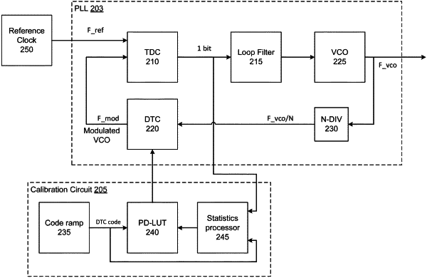
1. A clock generator calibration system, comprising:
a phased-locked loop (PLL) configured to generate an output clock signal; and
a correction circuit, comprising:
a code ramp configured to generate digital-to-time converter (DTC) codes; and
a statistics processor configured to:
sample values of a digital signal of the PLL;
determine a distribution of the sampled values of the digital signal of the PLL per each respectively received one of the DTC codes; and
generate a correction signal based on the distribution,
wherein the correction circuit is configured to generate a control signal based on the correction signal and a generated DTC code from among the generated DTC codes, and to cause the PLL to adjust a frequency signal of the PLL to provide an adjusted frequency signal based on the digital signal of the PLL, the digital signal being generated based on the adjusted frequency signal.
|