| CPC H03L 7/0807 (2013.01) [G11C 11/4093 (2013.01); G11C 11/4099 (2013.01); H03L 7/04 (2013.01); H03L 7/0816 (2013.01); H03L 7/1072 (2013.01); H03L 7/187 (2013.01); H03M 1/0626 (2013.01); H03M 1/0687 (2013.01); H03M 1/0836 (2013.01); H03M 1/182 (2013.01)] | 20 Claims |

|
1. An apparatus comprising:
a multi-modulus divider (MMD) having a divider input, a divisor input, and a divider output;
a phase detector having a first clock input a second clock input, and a PD output, the second clock input coupled to the divider output; and
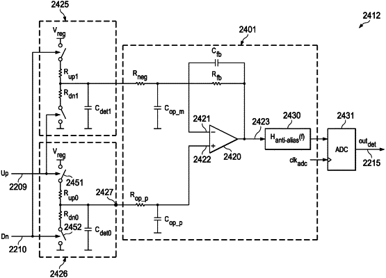
a phase to digital converter (P2DC) having a P2DC input and a P2DC output, the P2DC input coupled to the PD output, and the P2DC output coupled to the divisor input, the P2DC including a filter and an analog to digital converter (ADC) coupled between the P2DC input and the P2DC output, the ADC configured to provide a digital signal representing a frequency ratio between a first clock signal at the divider input and a second clock signal at the first clock input.
|