| CPC H02M 3/33592 (2013.01) | 20 Claims |

|
1. A method of operating a flyback converter, comprising:
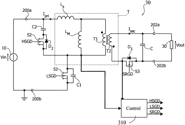
during a first time interval of a switching cycle, closing a first electronic switch and opening second and third electronic switches, the first electronic switch being coupled to a primary winding of a transformer between first and second input terminals for receiving an input voltage, the first electronic switch and primary winding being coupled to each other at a phase node and a capacitance is associated with the phase node, the second electronic switch and a clamp capacitor being coupled to each other as an active clamp circuit coupled in parallel with the primary winding, the third electronic switch and a secondary winding of the transformer being coupled between first and second output terminals for providing an output voltage, wherein closing the first electronic switch during the first time interval couples the primary winding to the input voltage and causes a current flowing through the primary winding to increase, thereby storing energy in the transformer;
during a subsequent second time interval of the switching cycle, opening the first electronic switch, and keeping open the second and third electronic switches, whereby the current flowing through the primary winding charges the capacitance associated with the phase node;
during a subsequent third time interval of the switching cycle, keeping open the first electronic switch and closing both the second and third electronic switches, which couples the clamp capacitor with the primary winding and the current flowing through the primary winding charges also the clamp capacitor, wherein the third time interval ends when the current flowing through the primary winding reaches zero;
during a subsequent fourth time interval of the switching cycle, keeping open the first electronic switch, keeping closed the third electronic switch, and opening the second electronic switch, whereby the current flowing through the primary winding is zero and the energy stored in the transformer is released via a current flowing through the secondary winding; and
during a subsequent fifth time interval of the switching cycle, keeping open the first electronic switch, closing the second electronic switch, and keeping closed the third electronic switch, whereby the clamp capacitor is electrically coupled in parallel with the primary winding, whereby the clamp capacitor and a leakage inductance form a resonant circuit having a given resonance period, and wherein the fifth time interval ends after one or more half-periods of the resonance period.
|