| CPC H02M 3/158 (2013.01) [H02M 1/32 (2013.01); H02M 1/36 (2013.01); H02M 3/07 (2013.01)] | 17 Claims |

|
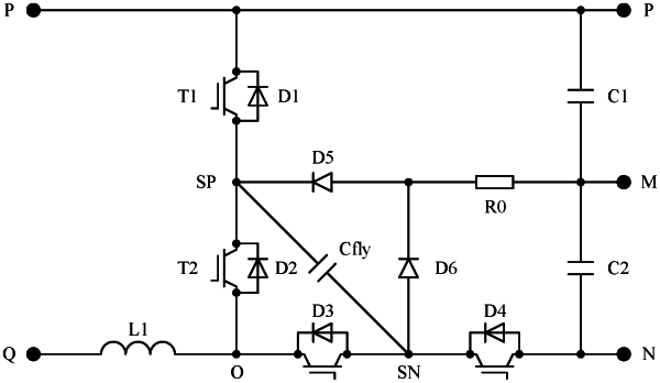
1. A direct current (DC)-DC converter, comprising:
a bus having a positive end, a negative end, and an intermediate node;
a first switch device having one end coupled to the positive end of the bus and another end coupled to a first intermediate node;
a second switch device having one end coupled to the first intermediate node and another end coupled to a reference end;
a third switch device having one end coupled to the reference end and another end coupled to a second intermediate node;
a fourth switch device having one end coupled to the second intermediate node and another end coupled to the negative end of the bus;
a first capacitor having one end coupled to the positive end of the bus and another end coupled to the intermediate node of the bus;
a second capacitor having one end coupled to the intermediate node of the bus and another end coupled to the negative end of the bus;
a flying capacitor having a positive end coupled to the first intermediate node and a negative end coupled to the second intermediate node; and
a protective circuit having a clamping unit and a buffering unit, wherein the first intermediate node and the second intermediate node are coupled to the intermediate node of the bus through the protective circuit.
|