| CPC H02M 1/081 (2013.01) [H02M 1/088 (2013.01); H02M 1/32 (2013.01); H02M 5/2573 (2013.01); H02M 5/293 (2013.01); H02M 7/06 (2013.01); H05B 39/04 (2013.01); H05B 39/044 (2013.01); H05B 39/048 (2013.01); H05B 45/10 (2020.01); H05B 45/37 (2020.01); H05B 45/3725 (2020.01); H02M 1/0006 (2021.05); H02M 1/0012 (2021.05); H05B 45/375 (2020.01); H05B 45/38 (2020.01); H05B 45/39 (2020.01)] | 20 Claims |
|
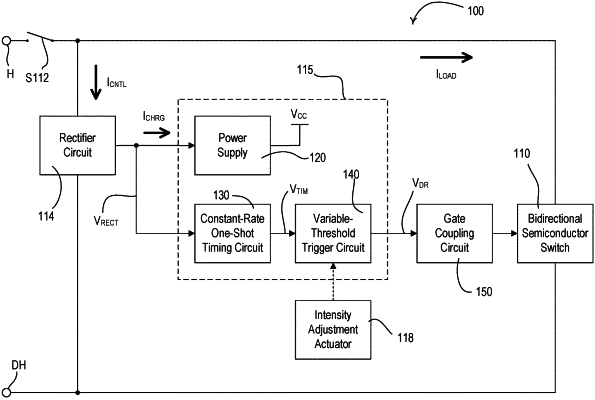
1. A load control device for controlling power delivered from an alternating-current (AC) power source to an electrical load, the load control device comprising:
a thyristor adapted to be electrically coupled between the AC power source and the electrical load, the thyristor having first and second main terminals through which current can be conducted to energize the electrical load and a gate terminal through which current can be conducted to render the thyristor conductive;
a gate coupling circuit electrically coupled between the first main terminal and the gate terminal of the thyristor to conduct current through the gate terminal of the thyristor;
a controllable switching circuit electrically coupled in parallel with the thyristor; and
a control circuit configured to generate at least one drive signal that is received by the gate coupling circuit, the control circuit configured to control a magnitude of the drive signal to a first magnitude to render the gate coupling circuit conductive and to a second magnitude to render the gate coupling circuit non-conductive;
wherein the control circuit is configured to:
control the magnitude of the at least one drive signal to the first magnitude to cause the gate coupling circuit to conduct current through the gate terminal of the thyristor to render the thyristor conductive at a firing time during a present half-cycle of the AC power source;
maintain the at least one drive signal at the first magnitude from the firing time until a transition time before the end of the present half-cycle to allow the gate coupling circuit to conduct current through the gate terminal of the thyristor again between the firing time until the transition time;
control the magnitude of the at least one drive signal to the second magnitude to render the gate coupling circuit non-conductive between approximately the transition time and the end of the present half-cycle; and
render the controllable switching circuit conductive to allow the controllable switching circuit to conduct current through the electrical load between approximately the transition time and the end of the present half-cycle.
|