| CPC H02M 1/0095 (2021.05) [H02M 1/0064 (2021.05)] | 17 Claims |

|
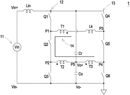
1. A power conversion circuit, comprising:
an input positive terminal, an input negative terminal, an output positive terminal and an output negative terminal, wherein the input negative terminal and the output negative terminal are connected to each other;
an input inductor, wherein a first terminal of the input inductor is coupled to the input positive terminal;
a first bridge arm comprising a first switch, a second switch and a third switch coupled in series, wherein the first and third switches are electrically connected to a second terminal of the input inductor and the input negative terminal respectively, the first and second switches are connected and form a first connection point, and the second and third switches are connected and form a second connection point;
a second bridge arm comprising a fourth switch, a fifth switch and a sixth switch coupled in series, wherein the fourth and sixth switches are electrically connected to the second terminal of the input inductor and the input negative terminal respectively, the fourth and fifth switches are connected and form a third connection point, and the fifth and sixth switches are connected and form a fourth connection point;
a transformer comprising a first winding, a second winding and a third winding, wherein the first winding is coupled between the first and third connection points, the second and third windings are coupled between the second and fourth connection points, the second and third windings are connected and form a fifth connection point, and the fifth connection point is connected to the output positive terminal;
an output capacitor connected between the output positive terminal and the output negative terminal; and
an auxiliary capacitor, wherein a first terminal of the auxiliary capacitor is electrically connected to the second terminal of the input inductor, and a second terminal of the auxiliary capacitor is electrically connected to the output positive terminal or the output negative terminal,
wherein a first terminal of the first winding is electrically connected to the second connection point through the second switch, and a second terminal of the first winding is electrically connected to the fourth connection point through the fifth switch.
|