| CPC H02J 3/16 (2013.01) [G05B 13/024 (2013.01); H02J 3/381 (2013.01); H02J 13/00002 (2020.01); H02J 13/00006 (2020.01); H02J 2300/10 (2020.01); H02J 2300/20 (2020.01)] | 22 Claims |

|
1. A system comprising:
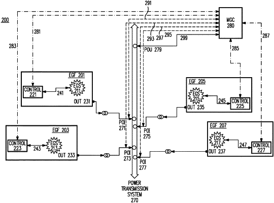
two or more energy generation facilities, each of the two or more energy generation facilities including an energy generation facility control unit for controlling the energy generation sources that are associated with that energy generation facility to provide a desired electrical energy output from that energy generation facility;
a power transmission system;
one or more Points Of Interconnection (POIs) for each of the two or more energy generation facilities to the power transmission system;
two or more energy generation facility output monitoring lines for collecting energy generation facility output data from each of the two or more energy generation facilities at their respective POIs, the energy generation facility output data including data indicating the output voltage of each of the two or more energy generation facilities at their respective POIs;
at least one Point Of Utilization (POU);
a POU monitoring line for collecting POU data from the POU, the POU data including data indicating the voltage at the POU;
two or more control signal lines for relaying control signals to each of the respective energy generation facility control units for each of the two or more energy generation facilities; and
a Master Grid Controller (MGC), the MGC controller being a dedicated MGC for the two or more energy generation facilities that is separate and distinct from the respective energy generation facility control units of each of the two or more energy generation facilities, the MGC controller providing control signals to the respective energy generation facility control units of the two or more energy generation facilities, the two or more energy generation facility output monitoring lines, the POU monitoring line, and the two or more control signal lines being operatively coupled to the MGC, the MGC monitoring and analyzing the POU data to determine if a voltage at the POU is within a desired POU voltage band, the MGC monitoring and comparing the energy generation facility output data of each energy generation facility at the POI of each energy generation facility to identify where reactive power is being exchanged between any of the two or more energy generation facilities wherein,
if the MGC determines the voltage at the POU is not within the desired POU voltage band, the MGC generates control signals to be sent to each of the respective energy generation facility control units of the two or more energy generation facilities via the two or more control signal lines, the control signals being used to adjust voltage control set points of each of the two or more energy generation facilities at their respective POIs in a manner necessary to bring the voltage at the POU into the desired POU voltage band,
further wherein,
if the MGC identifies reactive power is being exchanged between any of the two or more energy generation facilities, the MGC generates control signals to be sent to the respective energy generation facility control units of the two or more energy generation facilities via the two or more control signal lines, the control signals being used to reduce the exchanged reactive power between the each of the two or more energy generation facilities.
|