| CPC H01S 5/185 (2021.01) [H01S 5/005 (2013.01); H01S 5/04252 (2019.08); H01S 5/04254 (2019.08); H01S 5/18302 (2013.01); H01S 5/34333 (2013.01); H01S 5/34326 (2013.01)] | 6 Claims |

|
1. A light emission device outputting light forming an optical image along a normal direction to a main surface of a substrate, an inclined direction intersecting the normal direction, or both the normal direction and the inclined direction, the light emission device comprising:
a light emission unit; and
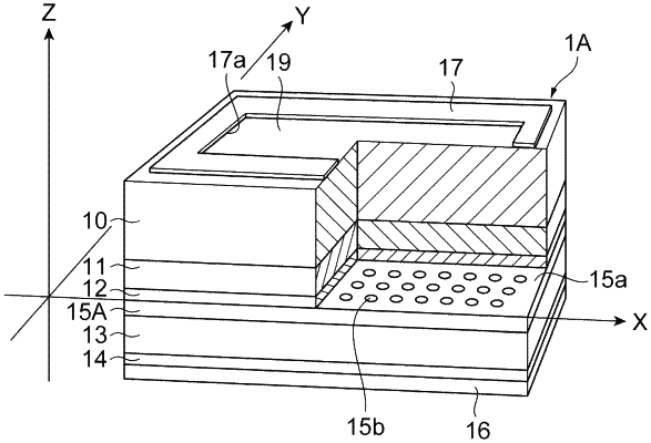
a phase modulation layer provided on the substrate and optically coupled to the light emission unit, wherein
the phase modulation layer has a base layer and a plurality of modified refractive index regions each having a refractive index different from a refractive index of the base layer,
in an XYZ orthogonal coordinate system defined by a Z-axis that coincides with the normal direction and an X-Y plane that coincides with one surface of the phase modulation layer including the plurality of modified refractive index regions, the X-Y plane including an X-axis and a Y-axis orthogonal to each other, where an imaginary square lattice configured of an M1 (integer of 1 or more)×N1 (integer of 1 or more) unit constituent regions each having a square shape is set on the X-Y plane and a unit constituent region R(x, y) specified by a coordinate component x (integer of 1 or more and M1 or less) in an X-axis direction and a coordinate component y (integer of 1 or more and N1 or less) in an Y-axis direction is set on the X-Y plane,
in the unit constituent region R(x, y), in a state where each of centers of gravity G1 of a plurality of modified refractive index elements constituting a modified refractive index region located in the unit constituent region R(x, y) is away from a lattice point O(x, y) which is a center of the unit constituent region R(x, y), an angle formed by a first line segment that extends from a lattice point O(x, y) to a center of gravity G2 defined by the plurality of modified refractive index elements located in the unit constituent region R(x, y) as a whole and a second line segment that passes through the lattice point O(x, y) and is parallel to the X-axis direction or the Y-axis direction is set such that light that forms an optical image is outputted,
a distance from the lattice point O(x, y) to each of the centers of gravity G1 of the plurality of modified refractive index elements located in the unit constituent region R(x, y) is greater than 0.30 times and is not greater than 0.50 times of lattice spacing of the imaginary square lattice, and
a distance from the lattice point O(x, y) to the center of gravity G2 defined by the plurality of modified refractive index elements located in the unit constituent region R(x, y) as a whole is greater than 0 and is not greater than 0.30 times of the lattice spacing of the imaginary square lattice.
|