| CPC H01Q 21/205 (2013.01) [H01Q 1/246 (2013.01); H01Q 1/28 (2013.01); H01Q 3/36 (2013.01)] | 15 Claims |

|
1. An antenna assembly comprising:
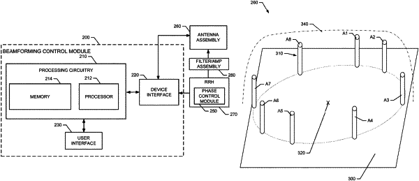
a plurality of antenna elements disposed in a circular pattern and equidistant from each other in angular separation relative to a common reference point at a center of the circular pattern,
wherein the antenna assembly includes or is operably coupled to a phase control module configured to apply selected phase fronts to each of the antenna elements to generate constructive and destructive interference patterns to define a directive beam in a desired direction,
wherein the selected phase fronts include no phase adjustment, a positive phase adjustment value and a negative phase adjustment value, the positive and negative phase adjustment values each having a same magnitude,
wherein a number of the antenna elements is eight and the angular separation is 45 degrees,
wherein the antenna elements are each disposed a distance about equal to a quarter wavelength of a frequency of operation of the antenna assembly away from a common reference point at a center of the circular pattern, and
wherein the positive phase adjustment value is 107° and the negative phase adjustment value is −107°.
|