| CPC H01H 85/046 (2013.01) [H01H 85/0241 (2013.01); H01H 85/055 (2013.01); H01H 85/463 (2013.01); H05K 1/0213 (2013.01); H05K 1/0272 (2013.01); H01H 2085/0275 (2013.01); H05K 2201/10181 (2013.01)] | 10 Claims |

|
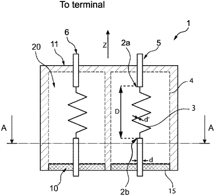
1. An operating device for light sources comprising a printed circuit board (20) with a conducting track (6) providing electrical connection from a terminal of an external power supply; a conducting track fuse (1) applied to the printed circuit board and connected to the conducting track (6), said conducting track fuse (1) comprising a first connection region (2a) connected to a portion of the conducting track (6) in contact with the terminal of the external power supply and a second connection region (2b), a burn-out region (3) arranged between the first connection region (2a) and the second connection region (2b); and a covering element (15) having two side walls (9), a delimiting wall (11) and a covering face (8), which is arranged over the first and second connection regions (2a, 2b) and over the burn-out region (3), wherein the burn-out region (3) and the covering element (15) are arranged relative to one another in such a way that the covering face (8) covers the burn-out region (3) and the delimiting wall (11) crosses the portion of the conducting track (6) connecting the first connection region (2a) of the conducting track fuse (1) and the terminal of the external power supply, and a cavity (7) is formed between the burn-out region (3) and the covering face (8) as a result of a height of the two side walls (9);
wherein each of the two side walls of the covering element (15) has an underside that is attached to the printed circuit board (20) and is attached by means of a connecting element (4), and further wherein said covering element (15) includes a gas vent (10) arranged opposite the delimiting wall (11) and between the two side walls, and wherein the second connection region (2b) extends through the gas vent (10).
|