| CPC G09G 3/3208 (2013.01) [G09G 2310/08 (2013.01); G09G 2320/0233 (2013.01); G09G 2320/041 (2013.01); G09G 2320/045 (2013.01); G09G 2330/045 (2013.01); G09G 2380/10 (2013.01)] | 7 Claims |
|
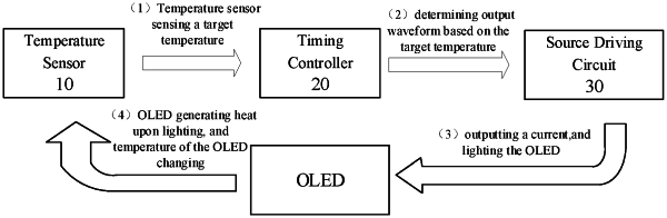
1. A driving device for a display panel, comprising: a temperature sensor, a timing controller, and a source driving circuit; wherein
the temperature sensor is connected to the timing controller, and is configured to sense a target temperature and output the target temperature to the timing controller, the target temperature comprising an operating temperature of the display panel;
the timing controller is further connected to the source driving circuit, the source driving circuit is further connected to a pixel in the display panel, and the timing controller is configured to control, based on the target temperature, the source driving circuit to output a drive signal with a target parameter to the pixel to drive the pixel to emit light; wherein target temperatures within different temperature ranges correspond to drive signals with different target parameters; and
a first corresponding relationship between the temperature ranges and candidate parameters is stored in the timing controller; and the timing controller is configured to: determine a target temperature range within which the target temperature falls; and determine a candidate parameter corresponding to the target temperature range as the target parameter; wherein
there is at least one of the following:
the target parameter comprises the waveform of the drive signal; and the first corresponding relationship comprises a first temperature range, a second temperature range, a third temperature range, and a candidate waveform of the drive signal corresponding to each of the temperature ranges; wherein
the candidate waveform corresponding to the first temperature range is a direct current waveform; the candidate waveform corresponding to the second temperature range is a negative bias pulse waveform; and the candidate waveform corresponding to the third temperature range is a positive bias pulse waveform; or
the candidate waveform corresponding to the first temperature range is a negative bias pulse waveform; the candidate waveform corresponding to the second temperature range is a direct current waveform; and the candidate waveform corresponding to the third temperature range is a positive bias pulse waveform;
wherein an upper limit of the first temperature range is less than a lower limit of the second temperature range, and an upper limit of the second temperature range is less than a lower limit of the third temperature range; or
the waveform of the drive signal is a negative bias pulse waveform; the target parameter comprises a duty cycle and a bias voltage of the negative bias pulse waveform; and the first corresponding relationship comprises a first temperature range, a second temperature range, and a candidate duty cycle and a candidate bias voltage of the drive signal corresponding to each of the temperature ranges;
wherein the candidate bias voltage corresponding to the first temperature range is greater than the candidate bias voltage corresponding to the second temperature range, and the candidate duty cycle corresponding to the first temperature range is less than the candidate duty cycle corresponding to the second temperature range, an upper limit of the first temperature range being less than a lower limit of the second temperature range; or
the waveform of the drive signal is a negative bias pulse waveform and the bias voltage of the drive signal is a target negative bias voltage; the target parameter comprises a duty cycle of the negative bias pulse waveform; and the first corresponding relationship comprises a first temperature range, a second temperature range, and a candidate duty cycle of the drive signal corresponding to each of the temperature ranges;
wherein the candidate duty cycle corresponding to the first temperature range is less than the candidate duty cycle corresponding to the second temperature range, an upper limit of the first temperature range being less than a lower limit of the second temperature range; or
the waveform of the drive signal is a negative bias pulse waveform and the duty cycle of the drive signal is a target duty cycle; the target parameter comprises a bias voltage of the negative bias pulse waveform; and the first corresponding relationship comprises a first temperature range, a second temperature range, and a candidate bias voltage of the drive signal corresponding to each of the temperature ranges;
wherein the candidate bias voltage corresponding to the first temperature range is greater than the candidate bias voltage corresponding to the second temperature range, an upper limit of the first temperature range being less than a lower limit of the second temperature range.
|