| CPC G02B 21/365 (2013.01) [G01N 21/6458 (2013.01); G02B 21/16 (2013.01)] | 9 Claims |

|
1. Fluorescence microscopy method comprising the following steps:
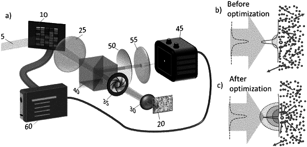
A. illuminating a scattering sample including one or more fluorescent emitters with a coherent excitation light beam having a wavefront with a first initial configuration C1 for exciting said one or more fluorescent emitters comprised in the scattering sample;
B. acquiring a first initial image F1 corresponding to a background image F1=FB of the scattering sample, through a pixel imaging unit, obtaining a speckle grain image;
C. selecting M target pixels PN, with N=1, . . . , M, of coordinates [xN, yN] belonging to an area of the first initial image F1 having fluorescence signals of at least one fluorescent emitters, each one of the M target pixels PN having a first initial intensity IPN1;
D. optimising the first initial configuration of the wavefront for each one of the M target pixels PN, for decreasing the speckle grain size of the first initial image F1 and obtaining a final image Ffin(IPNmax) of the scattering sample with a local maximum IPNmax of the fluorescence signal corresponding to a maximum intensity of the target pixels PN;
E. subtracting the first initial image FB of background, obtained at step B, from the final image Ffin(IPNmax), obtained at step D, for each one of the M target pixels PN, obtaining an image Fspeckle(PN) having only fluorescent signals coming from a speckle grain located at pixel [xN,yN] with intensity IPNspeckle, for each one of the M target pixels PN;
F. fitting the image Fspeckle(PN), obtained at step E, with a Gaussian function with free center coordinates, for each one of the M target pixels PN, thereby obtaining coordinates (XN, YN) and intensity IN in a xy plane;
G. generating an image FN containing a Gaussian distribution centered at coordinates (XN, YN) and with intensity IN, obtained at step F, and with a waist equal to an average size S of speckle grain of the scattering sample, for each one of the M target pixels PN; and
H. generating a final image of the sample by summing the M images FN obtained at step G, for each one of the M target pixels PN.
|