| CPC G01N 15/1434 (2013.01) [G01N 15/0205 (2013.01); G01N 15/1459 (2013.01); G01N 2015/1486 (2013.01)] | 13 Claims |

|
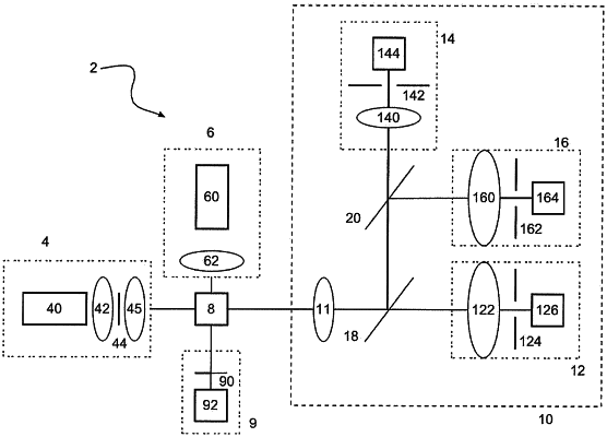
1. Electro-optical device for taking measurements of flow, comprising a measurement tank (8) through which a flow of fluid to be characterized flows, at least first and second guns (4, 6) for emitting light having separate spectra, a triggering gun (9) allowing small-angle diffraction to be measured and a receiving gun (10) allowing a measurement of attenuation and at least one fluorescence to be taken, wherein:
the first emitting gun (4) comprises a light source (40) having a center wavelength greater than 580 nm and defining a main optical axis perpendicular to the flow of fluid,
the second emitting gun (6) comprising a second light source (60), having a center wavelength of less than 580 nm and defining a secondary optical axis substantially orthogonal to the main optical axis and to the flow of fluid,
the first emitting gun (4) and the second emitting gun (6) are disposed on one side of the measurement tank (8), the receiving gun (10) is disposed on the other side of the measurement tank (8) along the main optical axis, and the triggering gun (9) is disposed on the other side of the measurement tank (8) along the secondary optical axis,
the receiving gun (10) comprises a detection channel (12) for measuring the attenuation and at least one detection channel (14) for measuring at least one fluorescence signal, as well as a single objective (11) for collecting the beam coming from the interaction of the light beam between the first emitting gun (4) and the second emitting gun (6) and the particles in the flow of fluid, said collecting objective (11) being arranged so that the light beam that it transmits is a beam substantially collimated along the main optical axis towards the detection channel (12) for measuring the attenuation, the receiving gun (10) forming a single mechanical unit at least a part of which is able to move with respect to the measurement tank (8),
the receiving gun (10) further comprising a first dichroic mirror (18) placed downstream of the collecting objective (11) where the light beam is substantially collimated, arranged for partially transmitting the light beam resulting from the interaction between the first emitting gun (4) and the particles in the flow of fluid towards the detection channel (12) for measuring the attenuation, and for partially reflecting the light beam resulting from the interaction between the second emitting gun (6) and the particles in the flow of fluid towards the at least one detection channel (14) for measuring at least one fluorescence signal.
|