| CPC G01M 3/02 (2013.01) [F15B 13/024 (2013.01); F15B 13/027 (2013.01); F15B 15/1409 (2013.01); F15B 15/204 (2013.01); F15B 15/22 (2013.01); F15B 19/005 (2013.01); F15B 21/10 (2013.01); F16K 31/12 (2013.01); F16K 37/0041 (2013.01); F15B 11/064 (2013.01); F15B 20/005 (2013.01); F15B 2211/30505 (2013.01); F15B 2211/40507 (2013.01); F15B 2211/50518 (2013.01); F15B 2211/50545 (2013.01); F15B 2211/5151 (2013.01); F15B 2211/5153 (2013.01); F15B 2211/555 (2013.01); F15B 2211/632 (2013.01); F15B 2211/6306 (2013.01); F15B 2211/6309 (2013.01); F15B 2211/6313 (2013.01); F15B 2211/7052 (2013.01); F15B 2211/857 (2013.01); F15B 2211/864 (2013.01); F15B 2211/865 (2013.01); F15B 2211/8606 (2013.01); F15B 2211/87 (2013.01); F15B 2211/8855 (2013.01)] | 19 Claims |

|
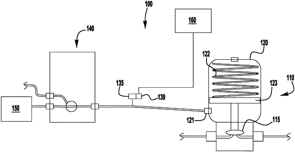
1. A method of monitoring performance of a fluid driven actuator for a valve, the fluid driven actuator including an actuator member movable from a normal position to an actuated position by fluid pressure applied to an inlet port of the actuator, the method comprising:
during a first time period, supplying pressurized gas through an actuator supply line to the inlet port of the actuator to move the actuator member from the normal position to the actuated position;
measuring pressure changes corresponding to a fluid flow condition in the actuator supply line during the first time period, the measured pressure changes defining a valve cycle pressure profile including a first inflection point indicating a decrease in a rate of pressure increase corresponding to an increased volume in the fluid driven actuator upstream from the actuator member resulting from movement of the actuator member from the normal position to the actuated position;
comparing the first inflection point with a first predetermined inflection point corresponding to an expected inlet pressure and time of actuation for movement of the actuator member from the normal position to the actuated position to identify a non-compliant condition in at least one of the valve and the actuator; and
generating an output communicating the identified non-compliant condition.
|